Your definition of active is more specialized than mine.But all of those elements are passive. Not active. The only active elements involved here are the tubes and/or transistors in the amplifier. Everything else is either resistive or reactive.
Your definition of the electronic component is broader since the voice coil is what I was considering.But that's ultimately just energy being returned to the system. Not from an external energy source.
The magnetic field is electromagnetically part of the inductor which is an electronic component considered a normal part of the electrical circuit while the cone is not part of the circuit.You mean like how the collapsing magnetic field around an inductor is being converted back to electrical energy?
An inductor can only convert a finite amount of stored energy back into electricity while a motor like a speaker used in reverse can do it indefinitely. A battery is not even considered a generator since its energy is only stored also.Which takes me back to my previous question. How is it exactly that a speaker is an AC generator but an inductor isn't?
I propose we retire this line of discussion.

traderbam said:By that definition a speaker isn't "active". But it does rely on a permanent magnet which is an "external" field source as opposed to an external voltage source as it were.
But it isn't active. Which was my point.
In any case I think your questions are about what the differences are between motors, ac generators and inductors.
Actually my questions are about what I asked originally. Which was:
What's the fundamental difference between the back EMF of the loudspeaker and the back EMF of any other RLC resonant circiut?
The answer it appears, disregarding issues wholly irrelevant to the issue of the supposed "FCD" such as flicking the cone with your finger, is "none."
Electrically, the fundamental behavior of a loudspeaker is that of an RLC resonant circuit. The back EMF of the speaker is fundamentally no different than the back EMF of an RLC resonant circuit.
se
Steve Eddy said:Electrically, the fundamental behavior of a loudspeaker is that of an RLC resonant circuit. The back EMF of the speaker is fundamentally no different than the back EMF of an RLC resonant circuit.
se
I think that's correct.
a 2ndary issue, one that some of us seemt o be arguing for, is that the RLC circuit does not represent the exact behavior of a real speaker in every circumstance. For example, the speaker emf may deviate fromt hat of the rlc circuit when it is overdriven.
That is true. But end of the day, the back emf from an rlc circuit is foundamentally the same as the back emf from a speaker. That seems to be the concensus here.
subwo1 said:The magnetic field is electromagnetically part of the inductor which is an electronic component considered a normal part of the electrical circuit while the cone is not part of the circuit.
Since the cone is fixed to the voice coil, that makes the cone decidedly part of the circuit.
An inductor can only convert a finite amount of stored energy back into electricity while a motor like a speaker used in reverse can do it indefinitely.
It can only do it indefinitely if you indefinitely keep putting energy into the system. Same holds true for an inductor.
se
Hi,
The circuit would be exactly the same without the cone.
Cheers,")
Since the cone is fixed to the voice coil, that makes the cone decidedly part of the circuit.
The circuit would be exactly the same without the cone.
Cheers,
Hi,
And if you pull the plug all active circuitry becomes rather passive all of a sudden...I wonder why...
Cheers,
It can only do it indefinitely if you indefinitely keep putting energy into the system. Same holds true for an inductor.
And if you pull the plug all active circuitry becomes rather passive all of a sudden...I wonder why...
Cheers,
You folks are really confusing me. First, a loudspeaker is NOT just an inductor. In fact, that is a very small part of the speaker circuit. The moving loudspeaker is a resonant SYSTEM all of its own that CAN be represented by an 'equivalent' R, L, and C model. Also, loudspeakers are microphones and pretty good ones at that, so any sound in the room can be put back into the loudspeaker an emf generated across the speaker terminals. What about a resonant cabinet? What about a port?
Loudspeakers may be 'simply' modeled as an equivalent RLC circuit, but that is not their complete response in the back EMF.
Loudspeakers may be 'simply' modeled as an equivalent RLC circuit, but that is not their complete response in the back EMF.
john curl said:You folks are really confusing me. First, a loudspeaker is NOT just an inductor.
No, they're not. Who said they were?
In fact, that is a very small part of the speaker circuit. The moving loudspeaker is a resonant SYSTEM all of its own that CAN be represented by an 'equivalent' R, L, and C model.
Yes. Because that's how it appears electrically to the amplifier.
Also, loudspeakers are microphones and pretty good ones at that, so any sound in the room can be put back into the loudspeaker an emf generated across the speaker terminals.
Sure. But what has that to do with the issue of FCD?
What about a resonant cabinet? What about a port?
Those also model as RLC equivalents.
Loudspeakers may be 'simply' modeled as an equivalent RLC circuit, but that is not their complete response in the back EMF.
Sure, the model doesn't account for microphonics, but then that hasn't anything to do with the FCD issue.
Remember, Graham's plot illustrating what he was referring to as FCD used an idealized loudspeaker model using nothing but ideal RLC components.
What prompted me to reply here was this notion that the "back EMF" of a loudspeaker is somehow fundamentally different than the "back EMF" of an RLC resonant circuit, looking at loudspeaker back EMF as a voltage source driving the amplifier's output (i.e. the "AC generator" notion) rather than the reactance of the energy storage mechanism that it is.
As an aside, it's interesting to note that with a typical dynamic loudspeaker driver, the "back EMF" is greatest at the driver's resonant frequency (Fs), and at that point, current and voltage are in phase and the loudspeaker presents a purely resistive load to the amplifier.
se
I'm looking for a "smilie" named "red herring" but can't find it.Sure. But what has that to do with the issue of FCD?
1st cycle distortion doesn't bother me...it's the distortion on all the subsequent cycles that I notice.

You seem to be mixing concepts up here. A speaker or motor or generator need not resonate at all. EMF is not a resonance effect. Resonant circuits do not have "back EMF" - this is to do with the opposition to force caused by a current flow within a magnetic field. Resonance is an entirely different thing.What prompted me to reply here was this notion that the "back EMF" of a loudspeaker is somehow fundamentally different than the "back EMF" of an RLC resonant circuit.
traderbam said:I'm looking for a "smilie" named "red herring" but can't find it.
Red herring? This thread is solely about FCD.
1st cycle distortion doesn't bother me...it's the distortion on all the subsequent cycles that I notice.
Hehehe. True. But the issue here is FCD.
You seem to be mixing concepts up here.
I don't believe I am.
A speaker or motor or generator need not resonate at all.
But dynamic loudspeaker drivers are a inherently resonant devices.
EMF is not a resonance effect. Resonant circuits do not have "back EMF"- this is to do with the opposition to force caused by a current flow within a magnetic field.
Back EMF is really nothing more than Lenz's Law in action and is a fundamental property of simple inductance. So a circuit which includes inductance, which includes RLC resonant circuits, do indeed have back EMF.
If you build the RLC loudpeaker model, the impedance peak at Fs is every bit as much due to back EMF as the impedance peak at Fs in a dynamic loudspeaker driver.
se
EMF from speakers and RCL circuits.
Hello,
I’m following this discussion with a lot of interest. I’m not sure what to think FCD, as I tend to think that it’s not a problem at audio frequencies.
However I’d like to give my point of view on the EMF debate related to the topic.
It’s quite easy to MODEL the speaker using an RCL circuit. This circuit is however a LINEAR circuit and therefore not capable of acting like the highly NONLINEAR system that a speaker is.
I’m not talking different speaker setups like ported or non ported systems, by a driver in general has pretty much no linear properties, but of cause it can be roughly described using the linear Thiele Small Parameters, small signal parameters.
The EMF generated by the normal linear model is based on a steady state scenario, and therefore it has IMO no meaning to talk about RCL circuits and it’s EMF in the discussion of FCD and speakers. If you want to take this stuff into account I believe it is necessary to use some form of NON LINEAR model – and just take my word for it – that will not make it easier to understand as it is quite heavy on the math side, and there are not many places that you can get the non linear model parameters needed for speakers.
Just my thoughts
If you want to know more about it try the www.klippel.de
\Jens
Re: EMF from speakers and RCL circuits.
what if you change the values of the rcl depending on some varianbles?
If you can, what does that say about the foundamental difference between a speaker and a RCL?
In my view, a system is linear or not isn't the point: any non-linear system will approach a linear system with small enough delta. and I don't think your speaker will generate totally different emf if driven with small enough of a signal. If that's the case, the rcl network (TS model) is essentially an electronic equavelent of a speaker (with small enough of a signal).
JensRasmussen said:It’s quite easy to MODEL the speaker using an RCL circuit. This circuit is however a LINEAR circuit and therefore not capable of acting like the highly NONLINEAR system that a speaker is.
\Jens
what if you change the values of the rcl depending on some varianbles?
If you can, what does that say about the foundamental difference between a speaker and a RCL?
In my view, a system is linear or not isn't the point: any non-linear system will approach a linear system with small enough delta. and I don't think your speaker will generate totally different emf if driven with small enough of a signal. If that's the case, the rcl network (TS model) is essentially an electronic equavelent of a speaker (with small enough of a signal).
peranders said:It seems that Graham is the only one that can answer this. Noone knows what Graham has invented.
I had asked when Graham invented FCD that he provide clear definition of FCD. However, he was too busy branding my requests as attacks so we never got time to understand clearly what he meant by FCD.
Well, I certainly hope that he come back to finish this discussion. in the past he had vowed to never come back and has broken the vows so I am hopeful that he will resurface soon.
i hold a lot of respect for Graham, as well as any member on this forum and I think if proven true, FCD can be a revolutionary step forward in our understanding of audio and human hearing.
but before anything is possible, we got to understand what FCD is. and we cannot do so without the person who invented FCD.
Re: EMF from speakers and RCL circuits.
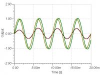
Except again, Graham illustrated FCD using using the purely linear model.
JensRasmussen said:The EMF generated by the normal linear model is based on a steady state scenario, and therefore it has IMO no meaning to talk about RCL circuits and it’s EMF in the discussion of FCD and speakers.
Except again, Graham illustrated FCD using using the purely linear model.
Attachments
The Klippel system can generate a distortion chart with a color-coded curve showing exactly what portion of the total distortion is due to back-EMF of the loudspeaker driver. Fun tool that Kippel is, if somewhat pricey.
Note that at least with long voicecoil/short gap designs (which includes the vast majority of woofers and fullranges presently made), the inductance value of the voicecoil will change, depending on the position of the voicecoil within the gap.
see:
http://www.diyaudio.com/forums/showthread.php?postid=58184#post58184
http://www.diyaudio.com/forums/showthread.php?postid=62641#post62641
and verified here:
http://www.diyaudio.com/forums/showthread.php?postid=66491#post66491
The voicecoil resistance can also change, depending on the instantaneous operating temperature (which can get pretty warm at high SPLs)
A wee bit more complex than a linear RCL circuit.
hth, jonathan carr
jcarr said:A wee bit more complex than a linear RCL circuit.
Yes, but yet again, Graham illustrated his FCD using all linear elements.
se
peranders said:It seems that Graham is the only one that can answer this. Noone knows what Graham has invented.
My question was very short and can probably be answered with not too many words.
There's always the last resort of actually reading the posts on the subject.
Hello,
All I wanted to say is that is that I don’t know weather or not the pheromone of FCD gets more obvious or less obvious using a non linear (Better model than the linear) and if the linear model in fact makes the whole thing seam worse/better than it actually is.
Does anyone know this – did anyone do sensitivity calculations comparing the two scenarios? Linear vs. Nonlinear loading of the amp?
Steve – what’s the graph legend on the graph? – thanks
\Jens
- Home
- Amplifiers
- Solid State
- First cycle distortion - Graham, what is that?