Indeed. I've just done a few more simulations at 20kHz.For f -> 0 it indeed becomes a simple negative-feedback amplifier, as I already mentioned at the end of post 86. What's more interesting is what happens at higher frequencies and how the distortion at the output then compares to the case without the inductor.
In a conventional output where the power transistors are biased on, the magnitude of Vbe swings is much much lower. So the Vbes distort the Miller feedback a little but that's tolerated, and usually there is another global NFB around the whole amplifier too.
In the Quad the Vbes dead zone is a huge 1.4V or so. To keep the circuit stable I think they had to use a relatively large 120pF compensation capacitor. You know, to stop it trying to be a radio transmitter. The combination of wild Vbe swing and large C, and the absence of any additional global NFB, made this distortion a show-stopper. Fixing this necessitated the invention of using a balanced bridge, which is very effective.
That's what I'm thinking. What do you think?
Last edited:
I think you just made a positive remark about current dumping, namely that a balanced bridge is very effective!
Anyway, Quad (or the Acoustical Manufacturing Co as they were called back then) already had experience with manufacturing the QUAD-303, which had a class-B output stage with quiescent current and thermal compensation. Hence, they must have known in advance what impact underbiasing an output stage has.
If you really want to know the historical backgrounds of current dumping, you need to do what historians of science do: look at all available written sources, try to track down as many still living people who worked for Acoustical in the 1970's as you can, interview them et cetera. You might also ask them what was wrong with the QUAD-303, because according to Peter Walker you only had to design a new product when there had been some major technical breakthrough or when there was something wrong with the old product. So why did they start the development of the 405 at all?
Indeed. I've just done a few more simulations at 20kHz.
In a conventional output where the power transistors are biased on, the magnitude of Vbe swings is much much lower. So the Vbes distort the Miller feedback a little but that's tolerated, and usually there is another global NFB around the whole amplifier too.
In the Quad the Vbes dead zone is a huge 1.4V or so. To keep the circuit stable I think they had to use a relatively large 120pF compensation capacitor. You know, to stop it trying to be a radio transmitter. The combination of wild Vbe swing and large C, and the absence of any additional global NFB, made this distortion a show-stopper. Fixing this necessitated the invention of using a balanced bridge, which is very effective.
That's what I'm thinking. What do you think?
As Peter Walker explains in the Wireless World Article http://www.keith-snook.info/wireles...d-1975/Current Dumping Audio Amplifer DCD.pdf
"steps are taken in the
design of the whole amplifier to ensure
that any such frequencies that may be
present do not embarrass the amplifier
performance within the audio range"
The parts for this are as I see R12 and C6. Covered by Keith Snook is the placement of C8
the 120pf capacitor which should be or is better placed in the 405 at the emitter of TR2
~ QUAD 405 Amplifier Information and Modification ~
To the class-B (or C) bias of the output stage: you can see the evolution in thinking in subsequent versions. The original had zero bias, but later on you see that first they relocated the base of the NPN to obtain some bias (1 Vbe) and later added an extra diode (D6).
The impression I get (but cannot prove) is that PW wanted to make a statement but later realized the class C was rather extreme")
Jan
The impression I get (but cannot prove) is that PW wanted to make a statement but later realized the class C was rather extreme
Jan
Attachments
Ah the good old 405 i can remember as a young audio engineer working in the trade We were all excited to receive the new quad 405 On receipt of the wonder we wired it up and were terribly disappointed with it
I much preferred the 303
I remember reading all the articles at the time of its release but did not believe a word
Tested the amp on sine waves and found it to be honest distortion was very for the time very low
However it could not and would not drive low impedance loads i think it was down to 28 watts into 4 ohms
But all credit to quad we still talk about it now
I have built 3 copies but i still believe a conventional design can sound better
Trev
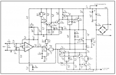
it's a high current class A driver stage ( 50 ma ) into Quasi comp all NPN output stage.
The PNP vas transistor can push several amps due to the buffers driving it.
the low side NPN has a PNP driver and 10 ohm base shunt for high speed.
the updated version has a diode between the two to party bias them.
the crossover distortion is handled by the 47 ohm resistor from VAS to output.
it works very well.
The amp is a low gain current feedback design driven by an op amp with a gain of -10 ish that also performs servo duty.
Ah the good old 405 i can remember as a young audio engineer working in the trade We were all excited to receive the new quad 405 On receipt of the wonder we wired it up and were terribly disappointed with it
I much preferred the 303
I remember reading all the articles at the time of its release but did not believe a word
Tested the amp on sine waves and found it to be honest distortion was very for the time very low
However it could not and would not drive low impedance loads i think it was down to 28 watts into 4 ohms
But all credit to quad we still talk about it now
I have built 3 copies but i still believe a conventional design can sound better
Trev
Yes the low impedance capability was not good because of premature activation of the overload protection. Very soon, in later models, that was redesigned and the low imp handling went much better.
Reading about this issue gives you the impression that it was actually an oversight at design time.
Jan
On the early ones we used to have problems with them going DC at the output and in fact the shop had to pay for new Bass drivers This was later dealt with by a dc crowbar on the output .A nice bit of bodge problem solving
But I do admit for the time the style was very nice .As mentioned earlier I have made a no of clones but I prefer the class A amp not to do gymnastics
Trev
But I do admit for the time the style was very nice .As mentioned earlier I have made a no of clones but I prefer the class A amp not to do gymnastics
Trev
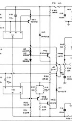
It's a tricky design challenge. The bridge can only stop Vbe feedback through the 120pF & 500 ohm parts. The bridge cannot stop parasitic feedback in the transconductance amplifier: for example the Ccb of the driver transistor Tr7 (RCA 40872). Quad has added C9 and C11 feedback paths too, presumably for stability reasons. I did not notice this mentioned in those articles but I would note parasitic feedback paths as another reason the Vbe feedback distortion can not be completely eliminated in practice.
Stability may also relate to Chris Daly's citation of Keith Snook's "proper location of C8". In the theoretical model, the 120pF and 500 ohm resistor should both connect to the same point of input to the transconductance amp. In the 405 that would mean 4 BJTs sequentially in the signal path of the NFB loop. Asking for trouble. I didn't read it carefully but I think Snook had to bypass one of them in order to relocate C8; maybe for this reason.
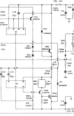
Another question in my mind concerns the output stage. The transconductance amp bias is about 45mA and this drives the BDY77s. Sort of short on current compared to conventional designs. The current limiter (about 8A?) is only on the positive rail but I doubt the negative could reach that with only 45mA drive current when the BDY77 has max gain of 140. Ok so you don't absolutely need 6A at normal listening into efficient speakers but it will run out of puff with 4 ohm loads and below.
The circuit is arguably more complex than the 303 and not as powerful. Does it sound better than the 303?
Some user comments: Quad 405-2 vs 303
Stability may also relate to Chris Daly's citation of Keith Snook's "proper location of C8". In the theoretical model, the 120pF and 500 ohm resistor should both connect to the same point of input to the transconductance amp. In the 405 that would mean 4 BJTs sequentially in the signal path of the NFB loop. Asking for trouble. I didn't read it carefully but I think Snook had to bypass one of them in order to relocate C8; maybe for this reason.
Another question in my mind concerns the output stage. The transconductance amp bias is about 45mA and this drives the BDY77s. Sort of short on current compared to conventional designs. The current limiter (about 8A?) is only on the positive rail but I doubt the negative could reach that with only 45mA drive current when the BDY77 has max gain of 140. Ok so you don't absolutely need 6A at normal listening into efficient speakers but it will run out of puff with 4 ohm loads and below.
The circuit is arguably more complex than the 303 and not as powerful. Does it sound better than the 303?
Some user comments: Quad 405-2 vs 303
Last edited:
In those days, BJT amps blew up a lot. Going class-C helped a bit, but did nothing to reduce high frequency float and shoot through, and lack of high power operation heat sink. I fixed a couple 405s. The slow power transistors available were the primary culprit, and the lack of power PNPs, and poor SOA. I think Harmon-Kardon were ahead of their time and used ross-coupled complimentary power transistors. Most amps were just barely stable because pushing slow transistors to 20KHz was close to the feedback limit. Most amps had very poor base pull-downs so when you loaded the amp with a long cable, it would become unstable, oscillate, float on, shoot through and SOA failure.
But today we have 40MHz BJT power transistors including PNPs, but most of all FETs and class-D which provide as good or better fidelity than class-B and much reduced heat.
But today we have 40MHz BJT power transistors including PNPs, but most of all FETs and class-D which provide as good or better fidelity than class-B and much reduced heat.
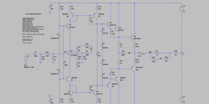
Original Quad 405 schematic from PW's article
FYI the bridge arrangement that was ingeniously used in the output stage is one of these: Wheatstone bridge - Wikipedia
FYI the bridge arrangement that was ingeniously used in the output stage is one of these: Wheatstone bridge - Wikipedia
Attachments
Last edited:
The current limiter (about 8A?) is only on the positive rail but I doubt the negative could reach that with only 45mA drive current when the BDY77 has max gain of 140.
Current limiting is on both positive and negative rails - the current sense resistors are the two 0R08 resistors on the schematic you posted. Mislabeled as R35 in both positions on your schematic
Good catch, thx. And TR8 allows more than 45mA to TR10 so the neg protection can kick in. Should have looked more closely at that bottom section.Current limiting is on both positive and negative rails - the current sense resistors are the two 0R08 resistors on the schematic you posted. Mislabeled as R35 in both positions on your schematic
Last edited:
Good catch, thx. And TR8 allows more than 45mA to TR10 so the neg protection can kick in. Should have looked more closely at that bottom section.
I remembered because I used a two short lengths of Constantan (acquired by devious means) to make the required 80 milliOhm resistors.
These days you can just search on Digikey and voila
Questions for current dumping gurus
So, I have a couple of questions for you:
1) If you were to put aside the commercial limitations that no doubt constrained Mr Walker (he wanted to make money), which aspects of the design would you spend money and effort re-engineering? And have the 520/606/909/QSP evolutions done this?
2) Is the output stage design in these amps constrained/complicated by NPN only BJTs?
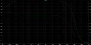
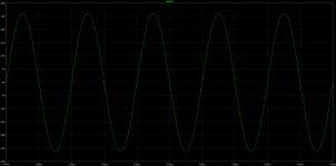
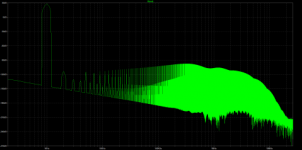
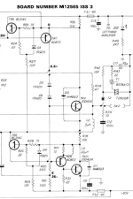
In the link below are measurements of an optimized 405-2, this achieves distortion of 0.0025% which is quite respectable for an amplifier with an unbiased output stage, I built some clones in the early 80s and measured the distortion at 0.0018. If the over-current protection is ignored the 405 is quite a simple design using only one opamp and 8 transistors
Stuart
Stuart
- Home
- Amplifiers
- Solid State
- Peter Walker and his current dumping principle