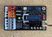
Finished (almost, temporary heat sink). The Si8752 (U1c) is soldered from the bottom, power terminals are doubled.
U1a ASSR-621 and U1b VOM1271 not tested yet.
Forum needs a like button... 🙂

What fets are you using now?Finished (almost, temporary heat sink). The Si8752 (U1c) is soldered from the bottom, power terminals are doubled.
U1a ASSR-621 and U1b VOM1271 not tested yet.
I used a PIC 8 pin micro on mine to detect DC.
I put a small mains transformer on the pcb to supply PIC power and mosfet rail power.
Mosfets tend to be expensive in low Rds high voltage on but if you dont go too high with volts cheaper lower voltage ones will do the job.
I put a small mains transformer on the pcb to supply PIC power and mosfet rail power.
Mosfets tend to be expensive in low Rds high voltage on but if you dont go too high with volts cheaper lower voltage ones will do the job.
What fets are you using now?
I use IPI037N08N3GXKSA1 (end-of-life part) but any TO-220 style 80-100V 3-5mR n-channel power mosfet will suit.
Attachments
Last edited:
I used a PIC 8 pin micro on mine to detect DC.
I put a small mains transformer on the pcb to supply PIC power and mosfet rail power.
Mosfets tend to be expensive in low Rds high voltage on but if you dont go too high with volts cheaper lower voltage ones will do the job.
the mains transformer should be placed as far as possible from the sound path (unless it is very well shielded)
I use IPI037N08N3GXKSA1 (end-of-life part) but any TO-220 style 80-100V 3-5mR n-channel power mosfet will suit.
The problem is that i can't find any... 🙁
I've used irf2805 with good results.
Its not so expensive, has RDS of 5mohm but only UDS of 55v
Its not so expensive, has RDS of 5mohm but only UDS of 55v
I've used irf2805 with good results.
Its not so expensive, has RDS of 5mohm but only UDS of 55v
Thanks!🙂
dadod,very good choice ,available and not expensive!
Last edited:
The problem is that i can't find any... 🙁
https://eu.mouser.com/Semiconductors/Discrete-Semiconductors/Transistors/MOSFET/_/N-ax1sf
Filters:
Through Hole
Package TO-262-3,TO-220-3,TO220AB-3,TO-220FP-3
N-Channel, 1 Channel
Vds 75-100V
Rds ON 3-5 mOhms
In Stock yes, Active yes
Apply Filters => Results: 56
Initial SSR3 documentation. Please report errors and ask questions 🙂 Thanks.
Thank you for such wonderful documentation.
I have some questions.
If i plan to use Aux psu for running the protection boards, is it mandatory to connect ground to protection board?
I want to implement my own ground(star ground), connected to Protwctive earth through Bridge rectifier and NTC.
What are those overcurrent protection settings, what do they do and how to implement different configuration you have mentioned.
Sorry upfront if my questions are stupid.
I am building Aleph2 and F5T in a single chassi(mono) so i need 4 speaker protection boards. I already have 2 but need 2 more. I want to see for myself how they both sound.
Last edited:
So if the -VDC rail of the PSU fails, this circuit will not trigger the relays open! I know from testing that what happens is that it can take several to many seconds before the DC voltage rises in the amp output before the DC trigger then opens the relays. The loss of the -VDC does not immediately cause the DC to increase above the trigger voltage. It is recommended that a simple -VDC sense transistor be put in the +VDC rail and if the -VDC fails i.e. a fuse blows after the PSU caps, then the +VDC is removed and the relays open immediately.
This is my understanding. The circuit is designed to protects the speaker. So it does not matter how long it takes for dc to appear at the output. When it does, the Mosfets (not relays) turn off and protect the speaker.
The other part of the circuit disconnects the Mosfets when there is too much current being drawn.
To protect the amp/ powersupply you would need to redesign the circuit/ PCB.
The other part of the circuit disconnects the Mosfets when there is too much current being drawn.
To protect the amp/ powersupply you would need to redesign the circuit/ PCB.
I realise they are MOSFETs! These are configured in what we call "MOSFET relays". We use MOSFETs because they dont arc and are less likely to fail closed/shorted than a mechanical relay.
It does matter how fast they turn off. You don't want DC running thru your speakers. DC can and will appear immediately on failure of the -ve rail and will slowly increase until it triggers the DC detection trannies. i don't accept that it is reasonable to allow an amp, fed with one rail, to remain connected to speakers. The speaker should be disconnected ASAP on ANY power interruption.
This circuit has no detection of too much current. What is too much? What diagram are you reading? The circuit detects DC of ~0.6 V which then opens the "relays". You could put 20A thru the speakers at 0.4 VDC and this circuit will not trip.
I did not mention protecting the amp or PSU. If you want to protect the drivers, then use IV circuits to protect the outputs. That can be done with 2 transistors and 2-4 resistors and maybe 2 diodes, OR use a optocoupler and voltage divider network.
i have built several different speaker protection circuits, including those using "MOSFET relays" using Si8752 MOSFET drivers. They all detect DC and loss of AC and over-temperature. Some of my amps use IV circuits but I have not used these a lot since they need tuning to avoid false triggering.
- Home
- Amplifiers
- Solid State
- SSR for speaker protection?