How can 0.4VDC produce 20A through a speaker (DCR 3 ohm) ?
captJackSparrow
Yes, the amp ground and the aux ground should be connected somewhere.
The implemented overcurrent protection is mainly about accidental short circuit.
I will try to add some calculations to the documentation.
captJackSparrow
Yes, the amp ground and the aux ground should be connected somewhere.
The implemented overcurrent protection is mainly about accidental short circuit.
I will try to add some calculations to the documentation.
Last edited:
Have to be a short in the cabling - not something DC protect circuits care about, since this cannot fry a speaker - the DC voltage offset detect is perfectly servicable for protecting speakers, and to limit current you'd use current limiting circuitry on the amp output stage, and of course fuses to prevent wiring catching fire if the semiconductors fail shorted.How can 0.4VDC produce 20A through a speaker (DCR 3 ohm) ?
Fuses - stop wires and transformers catching fire - only purpose of a fuse really.
output current limiting - stops an output stage burning up on a short-circuit, may also protects output devices from secondary breakdown if suitably designed.
speaker-protect circuit - protects speaker voicecoils from fusing if a large DC offset happens for some reason (clipping is one cause, large RF oscillations also perhaps) - nothing to do with handling short circuits or protecting the amp from drivers that are too low an impedance.
Would it be possible, or feasible, to extend the job of the dc protection circuitry to control power fets on the amplifier power rails caused by that dc on the output by a failed amplifier power fet, power supply diode/regulator failure, fuse, etc?
1. Class A can deliver high current at low voltage so although 20A might normally not be possible, up to 10A definitely is.
2. It might be possible to extend DC protection to FET protection but I haven't seen it done. Output (IV) limiting seems to be most popular way but purists would argue that these circuits can affect output quality. I would be surprised if anyone could hear the difference.
It all comes down to whether you want to spend money on circuits to protect FETs or if protecting your expensive speakers is good enough. Lateral MOSFETs are extremely rugged and so if you can shut off power quickly, it is unlikely that they will blow. Other types of FETs might not be so rugged.
Please share the gerber files as its a nice project to build as always wanted to change my relay/UPC1237 based circuits and boards.
Thanks and looking forward to the same.
Thanks and looking forward to the same.
The protection schematic from post 295 will not protect the speakers in all cases. Specifically, in the most dangerous cases for speakers, the protection with MOS-FET's will also break and will then burn the speakers.
Why? Simple! A short-circuited transistor will cause a very high current through the speakers. This current will charge the coil from the woofer filter with energy. When the relay opens, the energy in the coil will cause a very large overvoltage at the terminals of the MOS-FETs and the transistors will short-circuit. The transient voltage suppressor diode present at the terminals of the transistors will limit the voltage but if the energy is high it will also enter a short circuit because this is how it is designed to work.
Why? Simple! A short-circuited transistor will cause a very high current through the speakers. This current will charge the coil from the woofer filter with energy. When the relay opens, the energy in the coil will cause a very large overvoltage at the terminals of the MOS-FETs and the transistors will short-circuit. The transient voltage suppressor diode present at the terminals of the transistors will limit the voltage but if the energy is high it will also enter a short circuit because this is how it is designed to work.
Exactly!
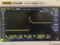
Do the following test: monitor the voltage at the terminals of the MOS-FET transistors with an oscilloscope when it switches OFF a current of minimum 5A through a coil of at least 2mH.
We'll talk after you will post the results from the scope.
Do the following test: monitor the voltage at the terminals of the MOS-FET transistors with an oscilloscope when it switches OFF a current of minimum 5A through a coil of at least 2mH.
We'll talk after you will post the results from the scope.
I tried it years ago.
PSU45VDC - 7R5 - 10mH - SSR(clamped by transil P6KE75CA)
So, the current was 6A.
And I don't want to talk to you.
PSU45VDC - 7R5 - 10mH - SSR(clamped by transil P6KE75CA)
So, the current was 6A.
And I don't want to talk to you.
Attachments
Last edited:
Only 180mJ. Most transistors will survive. How long the TVS will survive ???
"And I don't want to talk to you." OK, fair enough.
"And I don't want to talk to you." OK, fair enough.
0.18J is 0.18W for 1sec or 180W for 1msec
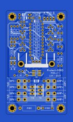
Did you notice the D6, D7 clamping diodes as well ?
My recommendation for max safety
- power the SSR3 by the poweramp psu
- apply diodes D6,D7,D8
- use current or VI limiter (SOA protection)
- immediately switch-off the SSR when short circuit happens
Did you notice the D6, D7 clamping diodes as well ?
My recommendation for max safety
- power the SSR3 by the poweramp psu
- apply diodes D6,D7,D8
- use current or VI limiter (SOA protection)
- immediately switch-off the SSR when short circuit happens
Last edited:


i have some spares left, off course free, just have to pay for shipping,look @Post 154Hi LKA, do you (or anyone else) have a couple of actual boards that you can sell ?
Thanks
Thanks Hicoco,
May I please have 2 ?
How do I go about paying you for the postage or any additional expense of sending it to the USA ?
If you have a paypal account, I could do that.
Please let me know.
Thanks
May I please have 2 ?
How do I go about paying you for the postage or any additional expense of sending it to the USA ?
If you have a paypal account, I could do that.
Please let me know.
Thanks
Yes PayPal, Should be around 7$ with tracking and 3$ without please PM me yours information for mailing.
- Home
- Amplifiers
- Solid State
- SSR for speaker protection?