fitted the spare preset and totally different behaviour. now allows me to set quiescent whatsit to 20mVi completely removed R81 both sides, seemed to be what the manual suggested.
i can try putting it back but the other side also has no r81 but the preset.
I'm hoping i damaged one preset when i bent its little legs to fit it across the pcb solder posts
that's good right! ?
")
no what can possibly go wrong from here .....
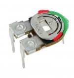
If you suspect the preset could be damaged (and they can be fragile) then replace it.
From what you say though, it does sound like the preset on even the good channel could be near to the end of its rotational range. That's not good for repeatability and reliability... it makes the adjustment to critical.
So one step at a time but I suspect we might end up making it like this with just the preset and no series resistor.
Attachments
Ideally (in a perfect world) yes, but given that 99.9% of amps always have an adjustable bias you have to argue that the time honoured approach works well.
It is a critical adjustment. To use a fixed resistor would mean being sure the bias is set correctly with the preset, then removing the preset without disturbing it and careful measure its value out of circuit. A suitable resistor (or combination of resistors) would then need to be chosen or calculated to replace it.
It is a critical adjustment. To use a fixed resistor would mean being sure the bias is set correctly with the preset, then removing the preset without disturbing it and careful measure its value out of circuit. A suitable resistor (or combination of resistors) would then need to be chosen or calculated to replace it.
This all sounds good as far as the amp being OK however there is real concern that the adjustment is to one ended and the preset is right up toward the end stop. That's bad simply because the end bit of track is where the resistive carbon layer is fixed to the pin and you don't want to be setting it in that area of track.
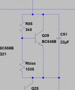
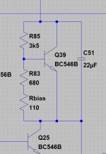
The total series resistance (that's R83 + preset) is 680 +110 or 790 ohms in total.
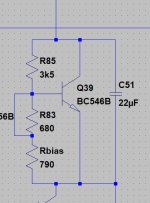
In order to get the preset in the middle of its range we need to lower the value of the 680 ohm... so lets link it out.
That now means the preset is the only resistance present in that series change and should be approximately in the middle of its range when you set the bias.
Keep using the bulb tester at this stage and always turn the bias fully down to begin with.
So it this to this....... Rbias is the preset of course.
The total series resistance (that's R83 + preset) is 680 +110 or 790 ohms in total.
In order to get the preset in the middle of its range we need to lower the value of the 680 ohm... so lets link it out.
That now means the preset is the only resistance present in that series change and should be approximately in the middle of its range when you set the bias.
Keep using the bulb tester at this stage and always turn the bias fully down to begin with.
So it this to this....... Rbias is the preset of course.
Attachments
We are stressing over the detail on this...
If you are happy that the preset isn't right at the end of its range then we are good to go. It has to be your call because I can't see it.
It is this 110 ohms you keep mentioning that suggests it is at the end of the range although the reading may not be accurate measuring in circuit. The actual value doesn't matter, as long as you can adjust smoothly up to the correct point and still not be at the end of the range.
3/8ths of the way around is perfect and right where we want it to be
So final checks then that all is OK such as the sensor in thermal contact with heatsink.
Now we turn the bias back down on both channels and remove the bulb. Now running on full mains we rebias to the desired value. I would set it on the low side at around 10 millivolts.
Last check is just to confirm that the DC voltage across the speaker output sockets is still close to zero.
Hopefully job done.
Also make sure the fuses are correct. Do not use under rated fuses because if one failed (when the amp was turned up loud for example) it would could cause damage to the amp/speakers.
The fuses are a safety feature for the user, but not necessarily in the amplifiers best interests.
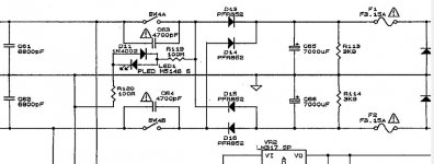
The manual doesn't seem to indicate whether the 3.15A fuses are time delay (marked T or AS) or quick blow (marked F). If you have the originals then check.
The fuses seem to be after the reservoir caps and so there should be no need for surge protection...... I wouldn't like to speculate on what was originally fitted there tbh.
The board or fuse holder might have a label saying what they are.
The fuses are a safety feature for the user, but not necessarily in the amplifiers best interests.
The manual doesn't seem to indicate whether the 3.15A fuses are time delay (marked T or AS) or quick blow (marked F). If you have the originals then check.
The fuses seem to be after the reservoir caps and so there should be no need for surge protection...... I wouldn't like to speculate on what was originally fitted there tbh.
The board or fuse holder might have a label saying what they are.
I would be seriously tempted to try an F3.1A fuses first.
And to check the amplifier with a dummy load/cheap 8ohms speaker many times before connecting expensive speaker/s.
I have found that an F3.1A supply rail fuse located AFTER the mains smoothing bank can power a ClassAB 100W amplifier in the very long term at all SPL loudness likely in the home.
And to check the amplifier with a dummy load/cheap 8ohms speaker many times before connecting expensive speaker/s.
I have found that an F3.1A supply rail fuse located AFTER the mains smoothing bank can power a ClassAB 100W amplifier in the very long term at all SPL loudness likely in the home.
I think we might be winningWe are stressing over the detail on this...
listened very happily on headphones last night !
take a bow mr mooly !


You're very welcome, and its good to have a successful outcome.
Changing electrolytics will not alter any DC conditions so no worries there.
Hard to say about the hum. It may be 'normal' for that model as many amps are not totally silent. Basic checks are always with nothing connected to the inputs (so just amp and speakers) and to initially see if the hum varies with the volume control or not. Even if it can not be improved, its good to know where it comes from and why.
it's only on one channel oddly.You're very welcome, and its good to have a successful outcome.
Changing electrolytics will not alter any DC conditions so no worries there.
Hard to say about the hum. It may be 'normal' for that model as many amps are not totally silent. Basic checks are always with nothing connected to the inputs (so just amp and speakers) and to initially see if the hum varies with the volume control or not. Even if it can not be improved, its good to know where it comes from and why.
I'll clean up the selector switch this morning which they all seem to need at 30+ years old whether it helps or not then I'll leave it alone
well chuffed
- Home
- Amplifiers
- Solid State
- Cyrus 1 output transistor question. push-pull?