Imbalance in the rails has no effect... strange but true. This is set to +15 and - 40. No offset 🙂
So 5 mv is a great result.
So it is bias next.
Remember to securely attach the meter leads across one of the 0.22 ohm resistors simply because it is so easy in all the excitement to either not make a good connection (and so think its not working) or to slip and short something out.
So 5 mv is a great result.
So it is bias next.
Remember to securely attach the meter leads across one of the 0.22 ohm resistors simply because it is so easy in all the excitement to either not make a good connection (and so think its not working) or to slip and short something out.
Attachments
Also, as you turn the bias preset slowly the lamp may start to glow. That's normal and in fact that is a good check it is working as it should.
Just aim to see if you can set the desired voltage approximately. Cyrus say between 8 and 20 mv. If you can get to 20mv then that's great. Just confirm and then return the preset back to zero bias.
Just aim to see if you can set the desired voltage approximately. Cyrus say between 8 and 20 mv. If you can get to 20mv then that's great. Just confirm and then return the preset back to zero bias.
awesome. 24hr hiatus alas need to family etc 🙂 damn them 😉Imbalance in the rails has no effect... strange but true. This is set to +15 and - 40. No offset 🙂
So 5 mv is a great result.
So it is bias next.
Remember to securely attach the meter leads across one of the 0.22 ohm resistors simply because it is so easy in all the excitement to either not make a good connection (and so think its not working) or to slip and short something out.
the 'channel that burned out' biases to 20mV no problems. or any lower value i want.🙂
Just take it slow and steady.
The other channel however. stays at 0.1mV until a point on the preset similar to the other side where it shoots up to 120mV or more and lights the bulb.
backing it off i get 0.1mV.
There seems to be no middle ground.
I got it to 5mV but the slightest touch on the preset sends it rocketing up.
hmmm !!
kinda fun though. enjoying this learning process enormously
cheers !
That's odd.
So the originally faulty channel appears to be OK now ? (at least this far in anyway).
What exactly did you replace in this previously good channel ? Was it just the output transistors. If so, are they identical to the ones in the repaired channel.
Bias current that jumps suddenly can be a sign of instability (the amplifier bursts into oscillation).
i used 4 x 3055t for outputs , 2 per channel.That's odd.
So the originally faulty channel appears to be OK now ? (at least this far in anyway).
What exactly did you replace in this previously good channel ? Was it just the output transistors. If so, are they identical to the ones in the repaired channel.
Bias current that jumps suddenly can be a sign of instability (the amplifier bursts into oscillation).
i used BD139/140 for drivers.
only other change has been the addition of the bias setting presets
I guess I'll just work my way through every transistor on the board
so on the good channel i replaced the outputs. the drivers and the R81i used 4 x 3055t for outputs , 2 per channel.
i used BD139/140 for drivers.
only other change has been the addition of the bias setting presets
I guess I'll just work my way through every transistor on the board
This doesn't immediately sound like a semiconductor problem, at least not in way you may be thinking.
Let me be 100% clear on this.
Both channels have had the outputs replaced for 3055T's
The original burned up channel also had BD139/140's fitted for the drivers and the bias mod preset) done.
The previously 'good' channel (the one that now seems to be a problem) has also had BD139/140 fitted, and the bias mod.
In other words, have we identical transistor sets in both channels ? Is there any difference component wise between the two channels ?
(don't randomly start pulling transistors and so on to test... this is something different)
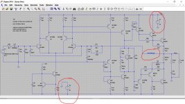
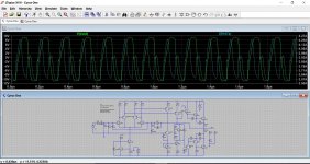
This shows what I think is happening. Look at the scales at the left and the right which show output voltage and current in the 0.22 ohm for normal bias and zero bias. This shows very high frequency oscillation of around 600kHz.
I have deliberately set the amp up to do this, however the basic design seems quite stable... so we have a puzzle.
The first things to check (assuming we have similar sets of transistors in each channel) is to make sure that the 'Zobel Network', which is that 0.1uF cap and 3.3 ohm connected to the output of the amplifier is OK. Worth checking the 3.3 ohm is intact, and also that there is continuity to and from the network.
Also make sure that there is no damaged or open print around the transistors you replaced in that channel.
Attachments

just realised i was measuring the Diode test points set to vDC not vAC !This shows what I think is happening. Look at the scales at the left and the right which show output voltage and current in the 0.22 ohm for normal bias and zero bias. This shows very high frequency oscillation of around 600kHz.
I have deliberately set the amp up to do this, however the basic design seems quite stable... so we have a puzzle.
The first things to check (assuming we have similar sets of transistors in each channel) is to make sure that the 'Zobel Network', which is that 0.1uF cap and 3.3 ohm connected to the output of the amplifier is OK. Worth checking the 3.3 ohm is intact, and also that there is continuity to and from the network.
Also make sure that there is no damaged or open print around the transistors you replaced in that channel.
they measure 22.1v AC as specified in the manual, so that's all good
no difference between the 2 channels, noThis doesn't immediately sound like a semiconductor problem, at least not in way you may be thinking.
Let me be 100% clear on this.
Both channels have had the outputs replaced for 3055T's
The original burned up channel also had BD139/140's fitted for the drivers and the bias mod preset) done.
The previously 'good' channel (the one that now seems to be a problem) has also had BD139/140 fitted, and the bias mod.
In other words, have we identical transistor sets in both channels ? Is there any difference component wise between the two channels ?
(don't randomly start pulling transistors and so on to test... this is something different)
checking I've put the drivers in the right places ie BD139 in q32 and BD 140 in q34 ....no difference between the 2 channels, no
they're right. the other thing that might have been disturbed by my fettling could be the thermal sensor system that reads off the back of the outputs to a transistor between each pair. I had to move the aluminium bars of course to get the outputs off the boardchecking I've put the drivers in the right places ie BD139 in q32 and BD 140 in q34 ....
So the rails all seem good and both channels are built up in the same way. Hmmm, interesting.
The thermal sensor would not cause this all or nothing problem, it would just allow the current to wander wildly with temperature.
How far round is the preset needing to be turned on the good channel to get the bias to adjust ? Is the range of adjustment around the middle or is it very 'one ended' ?
I mentioned instability and oscillation... but another possibility (although a long shot) could be something as simple as the preset having been damaged or the resistive track being cracked. That is one (unlikely but possible) scenario that would do this.
Also carefully visually check around the preset and make 100% certain that it isn't shorting anything nearby or that the unused leg isn't touching anything.
I'm thinking of trying another preset or even swapping them over.So the rails all seem good and both channels are built up in the same way. Hmmm, interesting.
The thermal sensor would not cause this all or nothing problem, it would just allow the current to wander wildly with temperature.
How far round is the preset needing to be turned on the good channel to get the bias to adjust ? Is the range of adjustment around the middle or is it very 'one ended' ?
I mentioned instability and oscillation... but another possibility (although a long shot) could be something as simple as the preset having been damaged or the resistive track being cracked. That is one (unlikely but possible) scenario that would do this.
Also carefully visually check around the preset and make 100% certain that it isn't shorting anything nearby or that the unused leg isn't touching anything.
it's just past about 2/3rds of the way round
the happy side i settled it at 16mV with the bulb in circuit. The preset measures 130R in that state.
the all or nothing side: at a very similar point all hell breaks loose from <1 mV to 150+ mV from the slightest snurge to the preset
I ordered a preset in a different format ie straight legged instead of angled because i didn’t know which might fit best. so I'll try that one and check the circuit tracks too.So the rails all seem good and both channels are built up in the same way. Hmmm, interesting.
The thermal sensor would not cause this all or nothing problem, it would just allow the current to wander wildly with temperature.
How far round is the preset needing to be turned on the good channel to get the bias to adjust ? Is the range of adjustment around the middle or is it very 'one ended' ?
I mentioned instability and oscillation... but another possibility (although a long shot) could be something as simple as the preset having been damaged or the resistive track being cracked. That is one (unlikely but possible) scenario that would do this.
Also carefully visually check around the preset and make 100% certain that it isn't shorting anything nearby or that the unused leg isn't touching anything.
the service manual says if you're blowing fuses : check Qs : outputs, drivers, pre-drivers and quiescent transistors and the fusible resistors. all that stuff is ok as far as i can tell from checking leg to leg with multimeter on diode test
the happy side i settled it at 16mV with the bulb in circuit. The preset measures 130R in that state.
the all or nothing side: at a very similar point all hell breaks loose from <1 mV to 150+ mV from the slightest snurge to the preset
I'll have a think 🙂 Have to go out this morning.
130 ohms sounds like it is at the end of its travel which could be a good thing as far as the fault goes.
Just remind me what value you have fitted for the fixed resistor in series with the pot, and what value pot you finally settled on using (was it a 2k type). We might just need to tweak the fixed resistor value.
Don't go altering anything just yet 🙂
Very quickly here is what to try.
Set the bias back to zero and confirm the bulb is out. Leave the bias on minimum.
Now replace the 680 ohm (was it 680 ohm fitted ?) that is in series with the pot (R83 I think from the blurry diagram) with a 470 ohm or lower.
Now try the adjustment again.
If you haven't a suitable resistor then you can even short out the 680 ohm and test.
The above assumes the preset is a 2k or 2k2 value .
Ideally the preset should be giving the right bias current with it somewhere in the centre of its travel.
Remember... if it is OK then we have to turn both channels back down and reset from scratch on full mains voltage. Also, if it is OK then I would recommend mirroring this action in the other channel because that will be a little one ended as well.
On full mains (no bulb) there is NO safety net and so turn up the bias really really slowly and at least initially, set it very much on the low side. We need to see that it is stable and that it doesn't run away with temperature. That is where that sensor comes in. It must be in good thermal contact with the heatsink.
 lets hope it is this that is the problem.
Set the bias back to zero and confirm the bulb is out. Leave the bias on minimum.
Now replace the 680 ohm (was it 680 ohm fitted ?) that is in series with the pot (R83 I think from the blurry diagram) with a 470 ohm or lower.
Now try the adjustment again.
If you haven't a suitable resistor then you can even short out the 680 ohm and test.
The above assumes the preset is a 2k or 2k2 value .
Ideally the preset should be giving the right bias current with it somewhere in the centre of its travel.
Remember... if it is OK then we have to turn both channels back down and reset from scratch on full mains voltage. Also, if it is OK then I would recommend mirroring this action in the other channel because that will be a little one ended as well.
On full mains (no bulb) there is NO safety net and so turn up the bias really really slowly and at least initially, set it very much on the low side. We need to see that it is stable and that it doesn't run away with temperature. That is where that sensor comes in. It must be in good thermal contact with the heatsink.
lets hope it is this that is the problem.i completely removed R81 both sides, seemed to be what the manual suggested.I'll have a think 🙂 Have to go out this morning.
130 ohms sounds like it is at the end of its travel which could be a good thing as far as the fault goes.
Just remind me what value you have fitted for the fixed resistor in series with the pot, and what value pot you finally settled on using (was it a 2k type). We might just need to tweak the fixed resistor value.
Don't go altering anything just yet 🙂
i can try putting it back but the other side also has no r81 but the preset.
I'm hoping i damaged one preset when i bent its little legs to fit it across the pcb solder posts
- Home
- Amplifiers
- Solid State
- Cyrus 1 output transistor question. push-pull?