Hello,
I was talking about the scans of the French magazines. I am not sure if you can put them online without permission. It is true you see them everywhere.
Once i made an Hiraga with the two power transistors close to each other on the same BIG heatsink.
But i think your drivers will not survive this heat.
Keeping the drivers at the same temperature will give you less DC drift.
Greetings, Eduard
Hello,
I was talking about the scans of the French magazines. I am not sure if you can put them online without permission. It is true you see them everywhere.
Once i made an Hiraga with the two power transistors close to each other on the same BIG heatsink.
But i think your drivers will not survive this heat.
Keeping the drivers at the same temperature will give you less DC drift.
Greetings, Eduard
Thanks!
I think you are right about the power transistors being too close.
If the circuit works, I may redesign the PCB.
And maybe double the output transistors too?
Sorry I've not posted but not had time. I have been listening to the Hiraga with my new Tannoy kensingtons and it sounds great but for some reason decided to check DC at the amps outputs. Set at 200mv I got readings of 190-199mv wth the multimeter then showing 1 so there's more than 200mv at times. Obviously I'm not happy about it. What can be the problem?
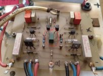
Okay I've taken some pics...
To be honest I can't see what could be changed - oh it was built in 1981 - the date is on the inside.


A lot of good work can be undone if the solder joins are not properly made.
I can see a lot of joins where solder has been used to "glue" fairly serious gauge cable - possibly rated at 10 amperes or more to various connection points. You need a more reliable connection than this - if the power transistors can be soldered directly to the board you will be better off.
Next best option would be to use a cable that fits through the small hole of the solder tags which will be easier to solder. The join needs to be mechanically sound.
Let's assume there is nothing wrong with your amp but age.
Try adjusting the potmeter to either side and adjust the offset voltage as close to zero as possible.
Then wait a while till the amp is warm, check offset and adjust if necessary.
Hopefully this is all there is to do...
Good luck!
Holy cow - yes it is. How did I miss that! So you think that will assist DC offset?
I bet a beer!
I've asked s mate whose a technician to take a look - too many high voltages for my liking!I bet a beer!
I've asked s mate whose a technician to take a look - too many high voltages for my liking!
Around this PCB there are only low voltages, nothing at all to worry about.
Just be careful that the screwdriver doesn't short anything.
I've adjusted then to read 40m - but this has meant turning them 3 quarters - that's a lot of drift - sure they weren't so high fur a reason?
There may be other reasons for the offset ... like ageing componets og solder joints. Read mjona's comments.
If the amp doesn't become unreasonably warm and sounds good, I wouldn't worry.
Does the offset drift after warming up? Hopefully closer to zero? If not, try adjusting a little more, like within +/- 10-20 mV
The problem is the pots are so loose (the screw) that just moving it changes values. I had them both at 40mv after ten mins warm (they don't go down with warm up they reach a steady figure). Even a slight over adjustment takes them into a - figure, ex -21 on the multimeter.
Are you turning both pots at the same time? You want to adjust one to take up half the offset, and then adjust the other one (often in the opposite direction) to take up the other half. You may need to go back and forth a couple of times.
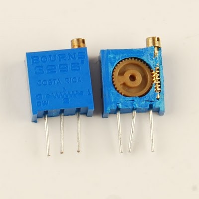
Those look to be 25-turn pots, so 3/4 of a turn is very little.
[Edit: in case you're wondering how that works, the screw drives a gear, which turns the actual pot:

Those look to be 25-turn pots, so 3/4 of a turn is very little.
[Edit: in case you're wondering how that works, the screw drives a gear, which turns the actual pot:

Last edited:
Disregard my adjust-half-way-comment. I just looked at the picture again and realised there's only one pot per channel, not two.
That's some pretty flaky results then. Damage to the pot resistive tracks, perhaps? (Are they both really squirrelly?) It might be instructive to desolder one of them and put it on a multimeter and see if you get smooth resistance changes when rotating the screw.
That's some pretty flaky results then. Damage to the pot resistive tracks, perhaps? (Are they both really squirrelly?) It might be instructive to desolder one of them and put it on a multimeter and see if you get smooth resistance changes when rotating the screw.
- Status
- This old topic is closed. If you want to reopen this topic, contact a moderator using the "Report Post" button.
- Home
- Amplifiers
- Solid State
- Idiot seeks help with Hiraga

