Could you tell me and others what SOTA means?
Thanks🙂
SOTA means State Of The Art
Keith
There is one exception that I forgot to mention.
Just in case of a gain of 1, with no Rg, the current that flows through Rf is the current needed for the minus input to get the output right and that is a pure current feedback, independent of Rf.
Hans
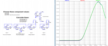
Hi Hans, There's something that puzzles me about your classifications. Please consider the attached.
You describe Figure 1 as "pure current feedback." Figure 2 is identical, with the exception of the addition of an ideal attenuator, so it too must be pure current feedback. You identify Figure 3 as employing voltage feedback, and I have added Figure 4 as kind of an amalgam of Figures 2 and 3.
Here's what bothers me: how can the types of feedback in Figures 2 - 4 be different if their inverting input currents are identical?
Attachments

I'm attaching a correction of an error in the definition of the parameter atten which nevertheless did not affect the calculations.
I'd also like to add that feedback literally means feeding a signal back to a destination. In Figures 2 - 4, the "feeds" and the "backs" are identical, so the "feedbacks" are identical, so their types must be identical. The feedback network topologies are different, but not the "feedbacks".
I'd also like to add that feedback literally means feeding a signal back to a destination. In Figures 2 - 4, the "feeds" and the "backs" are identical, so the "feedbacks" are identical, so their types must be identical. The feedback network topologies are different, but not the "feedbacks".
Attachments
Does the inv. input sinks of sources current?
M.
Although the inverting input terminal sources and sinks electron current it only sources current. This is based upon the condition that the current mirror as feeding into Rz can only source current.
The direction of electron current at the inverting terminal must match the direction of electron current being sourced from the current mirror. This is necessary for the device to function. Another way of looking at it is to say that because the current mirror cannot sink current, neither can the inverting terminal.
This can be seen in the absence of resistor Rg when unit current 1i is being sourced across Rf, as always causing Vin to be higher than V Out.
Current sinking, occurs into ground through Rg, whereupon difference currents between unit current 1i and i2 appear across the feedback resistor Rg as thereupon supporting voltage gain. i2 must be greater than 1i for this to occur.
Attachments
ffor,
I am stating what is understood by the professional engineering community and academia - not just repeating myself. These devices (of with, cumulatively, billions have been made) work flawlessly applying the concept and the mathematics of current feedback. This must be correct since I am not hearing that things are not working all over the pace - like video systems, T&M, telecoms etc which is where CFA's are used a lot. Is it possible that everyone got is completely wrong over the last c. 30 years with these devices? That all the errors in application fortuitously cancelled out so that the correct operation always resulted?
It is incumbent upon you to prove that this CFA approach is wrong, and that the correct approach is to treat it as a VFA. Thus far you have not shown that, despite many people trying to show you why your approach (or Moo Koo, or K. Aylward et al) is flawed. Look up 'Russell's teapot' for why it is up to you to prove your assertion, and not the other way around.
Re the resistor values for CFA assuming a narrow range - here's a thought experiment for you: Take a VFA with a gain of 10 in the non-inverting mode - for simplicity. Maintaining the 1:9 feedback network ratio, you can safely change the absolute values of the feedback network by 3 or 4 orders of magnitude (more if you have a JFET input amplifier) and still have an operational circuit. You cannot do that with a CFA because if the values are too low it will cease to operate and the same will apply when the values are too high.
Ergo, if the feedback resistor values in a CFA are confined to a narrow operating range for correct operation, it cannot just be a voltage divider action of the feedback network that determines the operating modality.
Last edited:
And ... It is completly new to me that the CFA concept which I know from the start now works only with values of resistors confined to a rather narrow range, I have not read that anywhere before and it's a proof that the concept is weak.
It has been mentioned several times before in various ways.
-RNM
now works only with values of resistors confined to a rather narrow range, I have not read that anywhere before and it's a proof that the concept is weak.
You seriously have not read that before? Then you have not read most of this discussion with any comprehension
Hi Chris,Hi Hans, There's something that puzzles me about your classifications. Please consider the attached.
You describe Figure 1 as "pure current feedback." Figure 2 is identical, with the exception of the addition of an ideal attenuator, so it too must be pure current feedback. You identify Figure 3 as employing voltage feedback, and I have added Figure 4 as kind of an amalgam of Figures 2 and 3.
Here's what bothers me: how can the types of feedback in Figures 2 - 4 be different if their inverting input currents are identical?
I agree with and fully support your findings, but let me try to describe my opinion a bit more in detail.
What I wanted to express is that with Rf and Rg both installed, both within a range that makes sense, you can regard this part as Voltage feedback as seen from the CFA's output.
Why, because when you increase or decrease the values of both Rf and Rg by a certain (moderate) percentage , the output voltage stays the same.
But the current from the output through Rf and Rg changes inversely proportional by the same percentage, implying that (output) voltage feedback is dominant.
BUT, from the junction of Rg and Rf, you definitely have a current feedback.
Because current from the IN- input results in a voltage at the CFA's output.
With Rg installed, current through Rf and Rg will be very much larger as the current from IN- causing the voltage feedback from the output being so dominant.
But without Rg, the only current flowing through Rf is now the current to IN-, hence we then have full current feedback.
This is in full agreement with your images that the current to IN- is in all cases the same for the same output voltage.
In fact it is a two stage feedback system. First as VFA with Rf and Rg installed , and starting from their junction to IN- as a CFA.
When Rg is left, the VFA part is eliminated and what remains is a CFA.
Hans
You are repeating yourself unusefully. I never contested that the so-called CFA configuration can do excellent job. By the way, remember that this CFA configuration existed before the differential input enters the amplifiers market, and that it is not restricted to the circuits with "diamond" input.ffor, I am stating what is understood by the professional engineering community and academia - not just repeating myself.
These devices (of with, cumulatively, billions have been made) work flawlessly applying the concept and the mathematics of current feedback. This must be correct since I am not hearing that things are not working all over the pace - like video systems, T&M, telecoms etc which is where CFA's are used a lot.
Is it possible that audio designers were not clever enough over 40 years before these 30 years to understand that the feedback of the amplifiers they conceived was controlled by current ? No, see Baxandall's comments on the Alexander's amplifier, one of the first claimed to be a CFA.Is it possible that everyone got is completely wrong over the last c. 30 years with these devices?
Did you already forget that I showed basic simulations of this ?Re the resistor values for CFA assuming a narrow range - here's a thought experiment for you: Take a VFA with a gain of 10 in the non-inverting mode - for simplicity. Maintaining the 1:9 feedback network ratio, you can safely change the absolute values of the feedback network by 3 or 4 orders of magnitude (more if you have a JFET input amplifier) and still have an operational circuit. You cannot do that with a CFA because if the values are too low it will cease to operate and the same will apply when the values are too high.
With a little of Sergio Franco's help :It is incumbent upon you to prove that this CFA approach is wrong, and that the correct approach is to treat it as a VFA. Thus far you have not shown that, despite many people trying to show you why your approach (or Moo Koo, or K. Aylward et al) is flawed. Look up 'Russell's teapot' for why it is up to you to prove your assertion, and not the other way around.
An externally hosted image should be here but it was not working when we last tested it.
The input stage is said "x1" which means it is a voltage follower circuit which makes Vn very nearly equal to Vp.
When the output of x1 sees a load, it delivers the necessary current to fullfill this equation.
This current comes from the power supply of stage x1. In all usual feedback amplifiers, it is amplified by the next stages up to the output which is connected to a feedback network.
This network is usually a voltage divider of two resistors (Rf and Rg, R2 and R1 in the figure above)
When the node between Rf and Rg is connected to the output of x1, the circuit becomes a closed loop negative feedback amplifier.
The output of x1 imposes its voltage Vn to the midpoint, delivering the necessary current to fullfill its role of voltage follower.
This current, called current error is determined by the voltage error, Vp - Vn.
Qualifying of current feedback a circuit whose loop is controlled by voltage is more than a semantic problem.
You would all be well served by putting forr on ignore for awhile and this thread would wind down to a deserved end.
I've even simulated that. It depends of what it is meant by rather narrow range.Originally Posted by forr
now works only with values of resistors confined to a rather narrow range, I have not read that anywhere before and it's a proof that the concept is weak.
You seriously have not read that before? Then you have not read most of this discussion with any comprehension
Hans Polak wrote
somewhat larger than confined.What I wanted to express is that with Rf and Rg both installed, both within a range that makes sense,
Last edited:
Thank you, Scott, but before the thread ends, it would be interesting to see your own interpretation to justify the naming of current feedback.You would all be well served by putting forr on ignore for awhile and this thread would wind down to a deserved end.
Thank you, Scott, but before the thread ends, it would be interesting to see your own interpretation to justify the naming of current feedback.
Would it matter, I don't think so. So why bother.
That's the aim of the thread.Would it matter, I don't think so. So why bother.
You would all be well served by putting forr on ignore for awhile and this thread would wind down to a deserved end.
Probably the best advice I’ve heard today.
Probably the best advice I’ve heard today.
I stopped trying to reason with him a number of posts ago when he ignored repeated requests to engage with my arguments. His response was to make a series of presentations on other topics.
In fact it is a two stage feedback system. First as VFA with Rf and Rg installed , and starting from their junction to IN- as a CFA.
When Rg is left, the VFA part is eliminated and what remains is a CFA.
Hans
Hi Hans,
I understand your reasoning. But the paradigm of two-stage feedback seems to me to have a problem - just what is the voltage feedback feeding back to? It's not the input stage - you stated that the input stage experiences current feedback. If there is no "back" for the "voltage feedback" to feed back to, then by definition, how can it be "feedback"?
Probably the best advice I’ve heard today.
It is a shame to call to ignore a member just because he disagrees with the majority.
I have no problem with the CFA name, but you can't disagree with the fact that the CFA feedback network impedance is low from the negative input view, and also that the ratio between Rg and Rf corresponds to the gain of the amplifier.
My conclusion is that we are in presence of voltage feedback, until it exists an "official" definition of current and voltage feedback.
I would be curious to have an example of what we can do with a CFA that cannot be done with a VFA.
It is a shame to call to ignore a member just because he disagrees with the majority.
That's not the reason, of course.
Jan
- Home
- Amplifiers
- Solid State
- Current Feedback Amplifiers, not only a semantic problem?