Current feedback amplifier
Thanks for your reply, Herve. Suppose you inserted a second voltage source between ground and the non-inverting input, one which presents a signal different from the first. What kind of feedback do you have now?
Suppose I zeroed the output of the first source but not the second. Then I reversed the situation so you have your proposed circuit. Does the type of feedback change with the levels of independent signal sources?
In the circuit you presented, The current flows from the output to the input where it has no effect. It also completely bypasses the op amp JFET input, and so has no effect on the op amp.
This does not satisfy the definition of feedback that I proposed:
"Feedback is the application of a signal derived from a first point in a circuit and applied to a second in a manner that influences behavior at the first."
What is your definition of feedback?
Current feedback amplifier
That's a voltage feedback amplifier.
There is no current (other than bias current) flowing in/out of the inverting input. You can keep the ratio of the feedback network resistors the same, but change the overall resistor values by orders of magnitude and it will still function correctly.
That's a voltage feedback amplifier.
There is no current (other than bias current) flowing in/out of the inverting input. You can keep the ratio of the feedback network resistors the same, but change the overall resistor values by orders of magnitude and it will still function correctly.
Yes, and holding the ratio constant, but changing the magnitudes of the resistances, you vary the current with little effect on the circuit.
Some current feedback, when you can vary the current and it makes no difference!
But I'm interested in how someone who calls this current feedback is thinking.
"IMO if "current" in "current-feedback amplifier" means "current flowing
between the negative feedback network and the inverting input", this name is
misleading because no current flows (excluding the small erroneous current).
In steady state, what is the normal condition of the circuit, the feedback
network (the voltage divider) produces following voltage that is equal to the
emitter voltage; so, (almost) no current enters/exits the inverting input.
This is a unique property of any bridge circuit including the "manual servo"
above where no current flows through the bridge element (regardless of how it
is low-resistive), and is named "bootstrapping". The manual servo (I have
attached it again for convenience) is an excellent illustration of this
phenomenon - if you vary the input voltage and I keep the compensating voltage equal to it, no current will flow through the galvanometer as much as
low-resistive it is... as though its resistance has become infinite. . ."
for, I regret to tell you this is just plain wrong. We've thrown words and math at you (in a nice way), but it does not seem to have worked.
There is no point to try to discuss this further with you. Its best you stick to your understanding of how things work if that is what helps you.
I am quite sure though that when (if indeed you do) apply a CFA opamp, you will no doubt follow the manufacturers guide lines very closely to get it to work properly, and that's all that matters 😀
for, I regret to tell you this is just plain wrong. We've thrown words and math at you (in a nice way), but it does not seem to have worked.
The "small error current" is what makes the amplifier work. They stare at the answer and still don't get it. Waste of time here.
It is a shame to call to ignore a member just because he disagrees with the majority.
There are far fewer flat earthers than there used to be... or maybe not.
I was under the assumption that this has been proved already.
< https://kenyatalk.s3.amazonaws.com/2018/02/219201_79143922b82746904cec71bdf5c1cae4.jpg >
The "small error current" is what makes the amplifier work. They stare at the answer and still don't get it. Waste of time here.
Well they're slowly starting to work out how feedback works, so there is progress 😎
Jan
Last edited:
I was under the assumption that this has been proved already.
< https://kenyatalk.s3.amazonaws.com/2018/02/219201_79143922b82746904cec71bdf5c1cae4.jpg >
The Flat Earth Society
Thanks for your reply, Herve. Suppose you inserted a second voltage source between ground and the non-inverting input, one which presents a signal different from the first. What kind of feedback do you have now?
Suppose I zeroed the output of the first source but not the second. Then I reversed the situation so you have your proposed circuit. Does the type of feedback change with the levels of independent signal sources?
In the circuit you presented, The current flows from the output to the input where it has no effect. It also completely bypasses the op amp JFET input, and so has no effect on the op amp.
This does not satisfy the definition of feedback that I proposed:
"Feedback is the application of a signal derived from a first point in a circuit and applied to a second in a manner that influences behavior at the first."
What is your definition of feedback?
Oups, sorry, I made a big mistake.
Voltage feedback amplifier :
Attachments

HiChris,Hi Hans,
I understand your reasoning. But the paradigm of two-stage feedback seems to me to have a problem - just what is the voltage feedback feeding back to? It's not the input stage - you stated that the input stage experiences current feedback. If there is no "back" for the "voltage feedback" to feed back to, then by definition, how can it be "feedback"?
And I understand your reasoning. I experience the CFA problem as trying to catch an eel swimming in oil.
Each time you think “I’ve got you” he slips through your fingers. But to answer your question first: The voltage feedback in my view is feeding back to the current feedback, that's the two stage feedback.
May I believe that we are in agreement that the current X flowing into IN-is the main orchestrator for all what’s happening at the output of the CFA ?
This X makes that exactly the right voltage is presented to IN- to achieve equilibrium. This is possible with (1) only Rf or with (2) Rf + Rg installed.
In both cases the values of the resistors Rf and Rg are bound to restrictions. They can’t be too high nor too low, for reasons well known.
In both cases input current X is translated into an output voltage X*Z(s).
For a gain of 0dB, the CFA output supplies current Y trough Rf, where Y=X and we have a 100% current feedback. This is what I see as a 1 step feedback process.
When Rg is added, a very much larger amount of current Y will be supplied by the output of the CFA to Rf and Rg, several orders of magnitude higher as X.
But from the junction Rf,Rg there is still this very much smaller current X flowing into IN- where X=Y–I(Rg).
As before this current X is causing the right amount of voltage to IN- to find equilibrium.
Because the current Y being used to create a voltage to IN- is practically independent of X, ( make Rf and Rg twice as large or twice as small and Y will become twice as small or twice as high) this is why I see it as a two-step feedback process.
First create an output voltage of X*Z(s) where X caused by V(in+) is primary flowing into Rg.
Then secondly feedback this output voltage divided by Rg/(Rf+Rg) to junction Rf,Rg and from here let current X (=again current feedback) find an equilibrium where X*Z(s) is V(in)*(1+Rf/Rg).
For the user of the CFA, gain is set by 1+Rf/Rg just as with a classical VFA, where he doesn't have to bother with input current X to IN-because this current is so small that it causes an error in the output voltage probably smaller as the accuracy of the used resistors Rf andRg.
Hans
Oups, sorry, I made a big mistake.
Voltage feedback amplifier :
Herve put 10K in series with the -input and look at the frequency response w/wo and tell me the current does not matter.
Herve put 10K in series with the -input and look at the frequency response w/wo and tell me the current does not matter.
Scott, you change the input resistor of this config, you change the open loop gain of the amplifier.
Herve, for the circuit you provided, it can be demonstrated that Vout = I(in-)* Z(s). I(in-) flows through the input stage from the feedback network; I(in-) = I(R1) - I(R12). I(R12) comes from the output stage.
This satisfies the definition of feedback that I proposed earlier. What is your preferred definition of feedback?
You can of course, argue that I(in-) = (V(in+ - V(in-) ) / Z(in-) and that therefore this is voltage feedback. However, this adds unnecessary complexity, and does nothing to deny the case for current feedback.
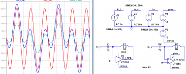
Consider the attached. We drive DC-stabilized CFAs in two ways:
(1) We apply a 1kHz voltage source to the (+) input and a 3kHz voltage source to the (-) input. These are of equal amplitude, and we see the difference of these signals at the CFA output. (The difference of the input signals multiplied by a factor of 1000 is displayed for reference.)
(2) We apply a 1kHz voltage source to the (+) input and a 3kHz current source to the (-) input. But only the 3kHz signal for the current source is apparent at the output. Oh, there is a 3kHz voltage difference between the inputs (no significant 1kHz component) - but this is only because Ohm's Law cannot be denied.
The CFA is responding to an applied current and ignoring an applied voltage.
This satisfies the definition of feedback that I proposed earlier. What is your preferred definition of feedback?
You can of course, argue that I(in-) = (V(in+ - V(in-) ) / Z(in-) and that therefore this is voltage feedback. However, this adds unnecessary complexity, and does nothing to deny the case for current feedback.
Consider the attached. We drive DC-stabilized CFAs in two ways:
(1) We apply a 1kHz voltage source to the (+) input and a 3kHz voltage source to the (-) input. These are of equal amplitude, and we see the difference of these signals at the CFA output. (The difference of the input signals multiplied by a factor of 1000 is displayed for reference.)
(2) We apply a 1kHz voltage source to the (+) input and a 3kHz current source to the (-) input. But only the 3kHz signal for the current source is apparent at the output. Oh, there is a 3kHz voltage difference between the inputs (no significant 1kHz component) - but this is only because Ohm's Law cannot be denied.
The CFA is responding to an applied current and ignoring an applied voltage.
Attachments
Scott, you change the input resistor of this config, you change the open loop gain of the amplifier.
But it's a "pure voltage" input but now the current (i.e. the -in sees the impedance connected to it) matters get the story straight.
Scott, you change the input resistor of this config, you change the open loop gain of the amplifier.
Yes, because the CFA is responsive to the current fed back into its input. The VFA is not. What better proof of the effect of current feedback could you ask for?
The "small error current" is what makes the amplifier work. They stare at the answer and still don't get it. Waste of time here.
Indeed 🙂
The voltage feedback in my view is feeding back to the current feedback, that's the two stage feedback.
Hans, I think I must ask you for your definition of feedback, because the statement you provided is not in accord with mine: "Current feedback" is not a "second point" in a circuit.
Yes.May I believe that we are in agreement that the current X flowing into IN-is the main orchestrator for all what’s happening at the output of the CFA ?
This X makes that exactly the right voltage is presented to IN- to achieve equilibrium. This is possible with (1) only Rf or with (2) Rf + Rg installed...
...In both cases the values of the resistors Rf and Rg are bound to restrictions.... As before this current X is causing the right amount of voltage to IN- to find equilibrium.
Up to here, I like what you've said.
Because the current Y being used to create a voltage to IN- is practically independent of X, ( make Rf and Rg twice as large or twice as small and Y will become twice as small or twice as high) this is why I see it as a two-step feedback process.
First create an output voltage of X*Z(s) where X caused by V(in+) is primary flowing into Rg.
Then secondly feedback this output voltage divided by Rg/(Rf+Rg) to junction Rf,Rg and from here let current X (=again current feedback) find an equilibrium where X*Z(s) is V(in)*(1+Rf/Rg).
For the user of the CFA, gain is set by 1+Rf/Rg just as with a classical VFA, where he doesn't have to bother with input current X to IN-because this current is so small that it causes an error in the output voltage probably smaller as the accuracy of the used resistors Rf and Rg.
Hans
I see this as unnecessarily complex. X = Vout / Z(s) = the difference between the Rg and Rf currents, which Vout ensures, and equilibrium is achieved. Two steps are not needed.
But it's a "pure voltage" input but now the current (i.e. the -in sees the impedance connected to it) matters get the story straight.
Yes, because the CFA is responsive to the current fed back into its input. The VFA is not. What better proof of the effect of current feedback could you ask for?
Preferred way to neutralize parasitic capacitances in VAS.
Preferred way to neutralize parasitic capacitances in VAS.
But it increases the distortion from the non-linear portion of the parasitics, again BTW current (displacement current in this case).
Preferred way to neutralize parasitic capacitances in VAS.
I don't see how your comment applies to the quote it responds to.
- Home
- Amplifiers
- Solid State
- Current Feedback Amplifiers, not only a semantic problem?