I tried using the VBIC model but just couldn't get it to behave any different than the standard model. I'd like to see someone who has actually used it show me why it's better.
Thank you for telling.Did you notice that most of those models are from 1988? Vaf=100 for most of them. I decided years ago to ignore any such models because most of the time they are not very good or are even complete garbage.
The models BC550C and BC560C that were needed in this case came from Cordell, the same as used by Scott.
90% of what's in this .lib is part of LTSpice and never get used by me, but I use this lib as a container and add whatever I need to keep everything together.
In general LTSpice is a fantastic tool, but it helps a lot when you know what you are doing. If not, don't expect to be able to build a Stradivarius.
LTSpice Sims helped me enormously preparing to build complex circuits.
It would be great if LTSpice came with models that were even closer to real life, but there will always remain a discrepancy.
Hans
In general LTSpice is a fantastic tool, but it helps a lot when you know what you are doing. If not, don't expect to be able to build a Stradivarius.
Hans

Hi Ian,Hi Hans,
I have tried a wide range of Rg values from 50 ohms to 5Meg for the LT1395 CFA and LT1364 VFA. The VFA open loop gain (Vout plot) drops from 79dB by 3dB when Rg=2.2Meg, about what I expected for a VFA. So the new jig can show the tipping point to becoming a CFA, or if you prefer, as you put it, "makes it look like" a CFA.
I know as you pointed out, that such high values are not used in practice. But my point is that there does exist values for the feedback resistors where the dominant type of feedback can change without any change in topology (arrangement of internals). This leads me (and many others) to the conclusion that the CFA is not fundamentally a topological arrangement of parts ... but rather a choice of resistor values (Rf//Rg) to suit the particular arrangement of amplifier parts.
I can understand that your way of thinking conflicts in this matter 😀
In the same way you can say that that there's no difference between a SUV and a limousine and that it is only a matter of sizes.
And you are right in both cases.
But I did not make the circular reasoning you suspect, because I'm not trying to prove anything from a previous assumption.
I have just made a tool that puts circuits called CFA by manufacturers in the CFA bucket an the others in the VFA bucket.
No prove, nothing further.
Every tool will have its exceptions and so will this one, but I have tried quite a number of circuits, and they all came out the way they are specified.
So instead of proving something or going into any semantical issue, my proposal was:
If it comes out as a CFA, let's call it a CFA, if not it's a VFA, and that without any further jiggling with resistor values.
Hans
Hi Hans,Hi Ian,
I can understand that your way of thinking conflicts in this matter 😀
....
If it comes out as a CFA, let's call it a CFA, if not it's a VFA, and that without any further jiggling with resistor values.
Hans
I'm happy and you seem happy. I've said enough so I'll sign off for now.
Thanks for sharing your thoughts and jigs.
Cheers,
IH
Hi Ian,Hi Hans,
I'm happy and you seem happy. I've said enough so I'll sign off for now.
Thanks for sharing your thoughts and jigs.
Cheers,
IH
A last word from my side to put things straight, because so far I have withheld my opinion on the semantical question.
I see the CFA as a second category type of VFA, let's say VFA-II.
Regarding the feedback it is still the feedback Voltage that counts and not the Current.
But inside a CFA starting from the minus input to Z(s) it's the Input Current that flows as the dominant information carrier.
In a VFA-I the Input Voltage is the dominant steering mechanism, a voltage that still has to be converted internally to a current also ending in a Z(s).
But from the outside both get their feedback from Voltage.
So in this second category VFA_II there are still differences to the first category, but within certain boundaries.
See it as two partly overlapping circles where in the overlap they show identical behaviour.
Outside the overlap they can do things that the other can't and vice versa.
So I'm on the side that semantically seen CFA is not what it is, but it certainly needed a different name and VFA-II would have been a silly name.
So why not accept CFA, it's just as a name.
Mr André Marie Ampère will be happy with so much attention.
Hans

Last edited:
Jan,Hans is your middle name Solomon? 😎
Jan
I would love to carry that name, ha, ha.
Hans
Currently, CFA is a silly name (I fear lightning strikes on me).So I'm on the side that semantically seen CFA is not what it is, but it certainly needed a different name and VFA-II would have been a silly name.
Imagine you are tyring to explain CFAs to students : "Current Feedback Amplifiers are circuits working under the control of voltage."So why not accept CFA, it's just as a name.
To a great number of them, the meaning will be, at first, the logical, initial one of forty years ago.
Hopefully you would teach students properly about the four types of feedback. ( shunt shunt, etc.) And then explain that CFA is just a name.
Hopefully you would teach students properly about the four types of feedback. ( shunt shunt, etc.) And then explain that CFA is just a name.
Yes I don't recall the textbooks using voltage vs. current at all in the definitions.
What about the word "vacuum cleaner" ?Currently, CFA is a silly name (I fear lightning strikes on me).
Imagine you are tyring to explain CFAs to students : "Current Feedback Amplifiers are circuits working under the control of voltage."
To a great number of them, the meaning will be, at first, the logical, initial one of forty years ago.
Are you cleaning vacuum, no of course not, but there is indeed vacuum involved to clean and there are probably dozens more "not so logical" examples.
Same way you can see CFA. The minus input sinks or sources current from the voltage feedback network. Is it therefore Current Feedback, no but there is indeed an important current involved.
There is one exception that I forgot to mention.
Just in case of a gain of 1, with no Rg, the current that flows through Rf is the current needed for the minus input to get the output right and that is a pure current feedback, independent of Rf.
Hans
There are other words for "vacuum cleaner": "hoover" (UK), "aspirator", "aspirateur" in french (that's not to say that french is more rigorous with the words).What about the word "vacuum cleaner" ?
Are you cleaning vacuum, no of course not, but there is indeed vacuum involved to clean and there are probably dozens more "not so logical" examples.
Most if not all my simulations show that the inverting input of a CFA sources current.Same way you can see CFA. The minus input sinks or sources current from the voltage feedback network. Is it therefore Current Feedback, no but there is indeed an important current involved.
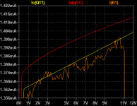
This schematics below depicts the case of gain of 1 by disconnectoion of Rg. It effectively shows that for usual values of Rf, the variations of the electrical parameters are extremly small. The most fixed is voltage Ve at the T1 emitter which is always a bit higher than voltage Vo at the output.There is one exception that I forgot to mention.
Just in case of a gain of 1, with no Rg, the current that flows through Rf is the current needed for the minus input to get the output right and that is a pure current feedback, independent of Rf.
The conclusion is that the inverting input of a CFA is a voltage controlled voltage source.
An externally hosted image should be here but it was not working when we last tested it.
When you repeat exactly the same thing over and over again, and fail to respond to to valid citricisms or genuine calls for clarification of your theory, you have entered the realm of dogma. If you are dogmatic in science or engineering, your mind is closed and you will not learn.
You can repeat your mantra ‘it’s a voltage input’ as many times as you like, it still does not alter the fact that a CFA will only work correctly if Rf and Rg are confined to a rather narrow range of values because they have to provide the correct amount of current in/out of the inverting input port. In a VFA these resistor values can assume a very wide range in absolute value (so not talking about gain range here). Further, in the ideal case, in a VFA no current flows into the inverting input (think about a JFET input VFA opamp for example).
On these matters alone, a CFA is fundamentally different from a VFA, and the derivations of the transfer equations fully support this - see the numerous applications notes from TI, ADI and academic Sergio Franco, plus excellent work by other posters on this thread.
Last edited:
When you repeat exactly the same thing over and over again, and fail to respond to to valid citricisms or genuine calls for clarification of your theory, you have entered the realm of dogma. If you are dogmatic in science or engineering, your mind is closed and you will not learn.
You can repeat your mantra ‘it’s a voltage input’ as many times as you like, it still does not alter the fact that a CFA will only work correctly if Rf and Rg are confined to a rather narrow range of values because they have to provide the correct amount of current in/out of the inverting input port. In a VFA these resistor values can assume a very wide range in absolute value (so not talking about gain range here). Further, in the ideal case, in a VFA no current flows into the inverting input (think about a JFET input VFA opamp for example).
On these matters alone, a CFA is fundamentally different from a VFA, and the derivations of the transfer equations fully support this - see the numerous applications notes from TI, ADI and academic Sergio Franco, plus excellent work by other posters on this thread.
Well said
Current Mode Amp is so much elegant, though...
Guys, this conversation is very entertaining and didactic. 🙂
For our edification, what I fail to understand, (amongst other topics) is:
What does the difference in calculated Ro represents in theoretical terms and what is its physical substrate?
Does the inv. input sinks of sources current?
Is the current (motion) the cause or the effect of difference in potential? (pressure gradient of the dielectric field)
Thanks very much,
M.
Last edited:
And you repeat exactly the same thing about my person. My very simple simulations hinder the CFA concept and may lead to uncomfortable situations for the theories.When you repeat exactly the same thing over and over again, and fail to respond to to valid citricisms or genuine calls for clarification of your theory, you have entered the realm of dogma. If you are dogmatic in science or engineering, your mind is closed and you will not learn.
You can repeat you mantra ‘it’s a current input’.... It is completly new to me that the CFA concept which I know from the start now works only with values of resistors confined to a rather narrow range, I have not read that anywhere before and it's a proof that the concept is weak.You can repeat your mantra ‘it’s a voltage input’ as many times as you like, it still does not alter the fact that a CFA will only work correctly if Rf and Rg are confined to a rather narrow range of values because they have to provide the correct amount of current in/out of the inverting input port.
All these brilliant works do no invalidate my humble simulations which anybody can replicate. Do not forget that the naming and the concept has been criticised by great names.On these matters alone, a CFA is fundamentally different from a VFA, and the derivations of the transfer equations fully support this - see the numerous applications notes from TI, ADI and academic Sergio Franco, plus excellent work by other posters on this thread.
Last edited:
Its the best source of SOTA amplifier design to date.
IMHO, of course.
Thx-RNMarsh
Could you tell me and others what SOTA means?
Thanks🙂
Hi Max,Current Mode Amp is so much elegant, though...
Guys, this conversation is very entertaining and didactic. 🙂
For our edification, what I fail to understand, (amongst other topics) is:
What does the difference in calculated Ro represents in theoretical terms and what is its physical substrate?
Does the inv. input sinks of sources current?
Is the current (motion) the cause or the effect of difference in potential? (pressure gradient of the dielectric field)
Thanks very much,
M.
Maybe you should read this
https://www.edn.com/electronics-blo...ansistor-?utm_source=Aspencore&utm_medium=EDN
And this
https://www.edn.com/design/analog/4458753/1/In-defense-of-the-current-feedback-amplifier
Hans
- Home
- Amplifiers
- Solid State
- Current Feedback Amplifiers, not only a semantic problem?