Millwood.
Every time I said anything about bipolars and circuitry on this, the JLH-69 bipolar amplifier forum, you talked about Mosfets.
The irony of that made me laugh. I said so in good humour, and without complaining.
Testing and real world interfacing solutions are far more complex than a narrowly defined set of computer simulations can reveal, and in this regard I hope I have left some ideas behind.
However, after your tirade in post 812, I sense something that I am better away from;
This column did not need that; I did need that; it's not on; and it's just not worth it.
Goodbye .............. Graham.
tschrama said:Based on all your comments and some additional suggestions by Geoff I made a simulation-format to fascilate simulation resulst.
Regards,
Thijs
you may have trouble simulating a mosfet output stage at 30v, tschrama.
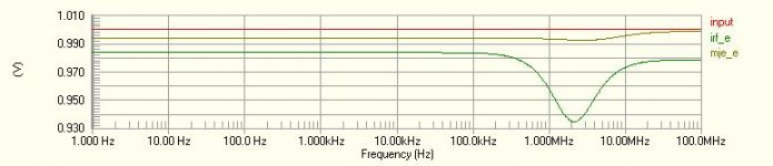
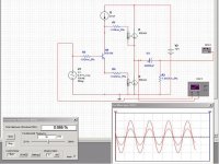
Also, I tried a quite emitter follower circuitry with mje15030 and irf540. here it is.
any thoughts? 🙂
Attachments
millwood said:
so what model did you use for the mje15030? and why are you convinced that mine (from protel dxp) is wrong?
I don't quite understand you and I stand behind my statements any time of the day. If indeed the model in protel is wrong for the device, I am happy to change it but I need someone to establish for me in a logic way that it is indeed incorrect.
I have no idea whether the protel model is representative of an actual MJE15030 or not. I used the model available at ON Semi's website.
The point I was making is that an MJE15030 (whichever model is used) cannot be used in simulation in place of a BD139 if you expect to get realistic results for a circuit that uses the latter.
You will have seen Graham's last post, and you wonder why I suggested that an apology was in order? I hope you are happy. We have lost a very knowledgeable and useful contributor to this thread. One who has provided insight and relevant information rather than a mass of useless and incorrect figures.
Geoff
Graham Maynard said:Millwood.
Every time I said anything about bipolars and circuitry on this, the JLH-69 bipolar amplifier forum, you talked about Mosfets.
The irony of that made me laugh. I said so in good humour, and without complaining.
I have mentioned many times over that I have lot of irf540s and I wanted to use them in some way shape or form. I entered in this endeavor with the hope that I would find something useful to others and hopefully others will benefit from my experience and the discussion surrounding this.
I have no agenda, either pro mosfet or pro bjt, other than to figure the best there is to use my irf. I hate the tone of this whole conversation (and defensiveness) that seems to implied that I doctored the simulations to show numbers in favor of the mosfet. I gave whatever my simulator gave me, and if you don't trust me, go download the simulator and do your own.
Graham Maynard said:However, after your tirade in post 812, I sense something that I am better away from;
I think that wouldn't be wise decision and I think anyone, you included, would be a valuable resource to this forum.
However it is your decision and i fully respect it and will not lose sleep over it.
Geoff said:The point I was making is that an MJE15030 (whichever model is used) cannot be used in simulation in place of a BD139 if you expect to get realistic results for a circuit that uses the latter.
I never represented the circuit using mje15030 as anything but. I stated upfront that I don't have it.
Also, you can see that the mje model in protel behaves similarly to that of irf. so I would suggest that there wouldn't be any advantage, model wise, to the irf.
Geoff said:One who has provided insight and relevant information rather than a mass of useless and incorrect figures.
Geoff
You are free to think of them as useless and incorrect and I disagree with you. But that's not the point of this discussion so we will just have to agree to disagree.
Graham can do whatever he elects to do and if he is unhappy because others disagree with him, so be it. and I will not spend anytime on that particular discussion as that's not the point of this particular thread.
millwood said:Also, I tried a quite emitter follower circuitry with mje15030 and irf540. here it is.
any thoughts? 🙂
it was a little odd to me that the protel models will show increasing gains for both devices, kind of counter-intuitive.
so on a 2nd thought, I tried 2n5551 (in protel dxp as well).
it looks normal, with gains decreasing with frequency.
I then went to onsemi and irf sites to compare the models and they are quit different from what protel had used.
so it does seem that protel may not have used the right models for mje and irf. but the irf model in protel doesn't hold an advantage (in terms of frequency responses) over the mje model in protel so directionally those conclusions should still hold.
the mje/irf models are quite interesting in that they are literally flat to 100mhz. Yet, simulations of jlh circuitry using them have lower open loop responses.
why would we get faster frequency response with slower models?
why would we get faster frequency response with slower models?
tschrama said:Any suggestions and comments are welcome,
Regards,
Thijs
tschrama: thanks for the efforts.
a few comments:
1) you may have trouble getting the mosfets running at 30v. I think that is a minimal figure. It is not uncommon for those devices to drop 5 - 6 v each.
2) I have seen clipping defined as voltage when THD reaches 3%.
3) some of the european transistors are tough to find. I don't have any of the bc/bd transistors in my simulator.
4) I am not clear as to what resistors are used on the driver: what's the emitter resistor? what's the upper / lower resistor for the bootsrap?
Thanks.
What happened to "leave your attitude at home"?millwood said:
OK. I got it.
so anyone of us listening to sine waves? no? then let's not to simulate with sine waves and use the stats based on sine waves.
anyone of us listening to square waves? no? let's not to simulate with square waves;
anyone of us using perfect zero resistance superconductors in our circuits? no? let's simulate all wires with resistors.
anyone of us using perfectly matched transistors? no? let's not simulate using exactly the same transistor models.
anyone of us listening to amps in RF free environment? no? let's simulate that as well.
anyoneo f us listening to simulations? no? throw your spice out of the window.
why don't we simulate with real music. why don't we feed our simulation with Britney Spears? no? you don't listen to Britney Spears? Michael Jackson? You listen to the Dixie Chicks? But I don't! so no more real life music.
You got the point?
...
that's one cheap shot class-less comment.
I simply hate this kind of conversations.
Hi all,
well I finaly got around doing some THD tests. For these tests I use a very simple wienbrigde oscilator tuned to 1.0KHz, around a NE5534 and a 3watt/220Volt lamp for amplitude stabilisation and a potmeter to tune to 0.7Vpp sine wave. I used a 24bit soundcard and personal computer to digitize the signal and generate the FFT graphs. Amplifier load was 8R2 dummy load parrallel to 100r+1K for back scaling of the output signal. Output voltage was 8Vpp. Averages of 16 FFT graphs. Level of the fundamental was -23dB.
Five test have been done:
oscilator straight in to soubdcard: THD = 0.003%
oscilator to MOSFET version at 250mA: THD = 0.014%
oscilator to MOSFET version at 1300mA: THD = 0.0022% (NOT a mistake)
oscilator to original 1969 version at 1300mA: THD = 0.027%
oscilator to straight in to soubdcard again: THD = 0.003%
Now don't jump to conclusions everbody. I really did my best to make good THD measurements and have checked everything twiwe at least.. I measured both my BJT channels and they were strikingly similar, I only did one MOSFET channel because my heatsink is not big enough to keep both channels running at high Iq.
I've saved the graphs and zipped them..here they come
G'night,
Thijs
Attachments
tschrama said:Hi all,
well I finaly got around doing some THD tests.
G'night,
Thijs
tschrama: good tests. do you have the ability to record waveforms as well? it would be interesting to see if slew rates are indideed symmetrical and different from vendor to vendor.
JLH versions
Millwood,
You wrote ‘My personal view (highly biased) is that going to dual rail or using complicated biasing mechanisms like in the 1996 design may just spoil the fun on this simplistic design, and doesn't gain much, as evidenced by all the "instability" problems people run into in various versions of the 1996 design.’
You probably have a point with regard to the stability issue, but when I listened to three different forms of Iq control in my 1996 circuit the least good sounding was the simple bootstrap version which used an Elna Silmic, the standard 1996 Iq circuit sounded significantly more open and transparent, a constant current source was the eventual circuit of choice. I believe the sonic signature of the bootstrap capacitor was the problem, the prospect of even a high quality large value electrolytic on the output is equally undesirable, at least for me. Then there is the feedback electrolytic capacitor, its removal again proving very beneficial.
For what it is worth, my theory is that the basic 1996 circuit sounds worse (in some ways) than the 1969 circuit, due mainly to the presence of the fixed regulator. Replacing this regulator with a ccs and listening to the result is persuasive.
If only there were such a thing as a sonically invisible capacitor.....dream on!
Tim.
a lot has been said about how the phase splitter works, the current matching on the upper / lower output devices and gain matching vs. distortion relationships.
Here is a very simple phase splitter, driving two perfect BJTs represented as two current-controlled-current sources (CCCSs, with a gain of 100x each).
THD figures and gains for the two devices (simulation done at 1vp /1khz + 5vDC on the input):
upper gain, lower gain, THD%
400, 100, 0.099%
200, 100, 0.081%
100, 100, 0.065%
100, 200, 0.053%
100, 400, 0.046%
it seems to suggest that higher gains on the lower output devices help but I need to understand why.
You can also replace the 2ma CCS with a 2.2k resistor. however, you pay for a performance penalty.
upper gain, lower gain, THD%
400, 100, 0.104%
200, 100, 0.386%
100, 100, 0.179%
100, 200, 0.099%
100, 400, 0.065%
again, using higher gain devices on the bottom seems to help.
Replacing the resistor with a bootstrap network helped considerably. The network i used is 10ohmx2+470uf. its performance:
upper gain, lower gain, THD%
400, 100, 0.264%
200, 100, 0.177%
100, 100, 0.101%
100, 200, 0.113%
100, 400, 0.164%
This one does suggest that gain-matched output devices helps.
Of course, this is a highly simplified picture. and if you factor in real life 'characteristics" of the output devices, it seems, intuitively, that matched pairs should help. But having said that, there seems to be a case made for using high gain devices on the bottom.
Exact reasons for that i don't know.
For those interested, you can replace the two CCCSs with voltage-controlled current sources (VCCS) to simulate how a perfect mosfet would work (it works, please allow me to assure you, 🙂). Of course, you will have to provide a voltage source for the bottom device by using a resistor.
my brief simulation with VCCSs suggests performance as measured in thd improved about 2-3 fold. I guess the driver stage is no longer loaded with VCCSs as it is with CCCSs.
Attachments
Re: JLH versions
Tim, you are one step ahead of me.
yes, you may very well be right on this, as indicated by the simulation with two perfect BJTs (current-controlled-current source) that I presented above. CCS-loading does seem to give the best THD figures (more so in the BJT world). so that would be the basis for your argument, if you will.
However, simulating with real-world parts (itself an oxymoron), I haven't been able to find a CCS load with better THD performance than a simple bootstrap arrangement. But then I haven't exhausted the world of CCS in my trial.
On top of that, simulations are no replacement for actual listening. so I don't think I am ready to conclude that bootstrap / single rail in the 1969 version is THE one.
Interestingly enough, a resistor will work just as well in a Voltage-controlled-current-source, aka perfect MOSFET, set up.
TimA said:a constant current source was the eventual circuit of choice.
Tim.
Tim, you are one step ahead of me.
yes, you may very well be right on this, as indicated by the simulation with two perfect BJTs (current-controlled-current source) that I presented above. CCS-loading does seem to give the best THD figures (more so in the BJT world). so that would be the basis for your argument, if you will.
However, simulating with real-world parts (itself an oxymoron), I haven't been able to find a CCS load with better THD performance than a simple bootstrap arrangement. But then I haven't exhausted the world of CCS in my trial.
On top of that, simulations are no replacement for actual listening. so I don't think I am ready to conclude that bootstrap / single rail in the 1969 version is THE one.
Interestingly enough, a resistor will work just as well in a Voltage-controlled-current-source, aka perfect MOSFET, set up.
not bad, not bad at all, 🙂.
I just finished breadboarding my very first jlh1969 BJT version, using 2n5401/tip41c/tip41cx2. bass is a little bit muddy but it is by no means optimized so I am not complaining. it sounded pleasant otherwise.
I used the same JLH1969 circuitry with one little modification: JLH used a 560ohm resistor as the lower resistor in the bootstrap. I did that too at the beginning and blew two pairs of my MJE15030 (which I initially used). I did some simulation and found that everything else being equal, using the MJEs will cause considerablly higher Iq.
so I instead used a 2.2k resistor in place of the 560ohm (I actually started out with tip41Cs and put two 10ohm power resistors to their emitters to be safe. After making sure that it worked, which it did, I replaced the 10ohm resistors with 0.47ohm resistors. Iq is 0.27v/.47=0.5amp (a little bit on the low side). I will replace the tips with mjes tomorrow to see if I hear anything.
I also ran a version where I used 2sc4793 as the driver. It sounded brighter and clearer than the tip at the driver position.
Need to experiment with this a little bit more.
one quick thing i noticed is that the bjt version doesn't have nearly as severe a turn-on inrush current problem as the mosfet version does. the turn-on current in the bjt is about 1amp (2x of bias) where in the mosfet version it can reach 5-6amp (4-5x of bias current).
the bjt version has a clear advantage over the mosfet version in this department.
the bjt version has a clear advantage over the mosfet version in this department.
Is it remotely possible that we can get back on to the subject of this thread ie the JLH amplifier and not a derivative that should be the subject of another thread? Has anyone a response to the last relevant question ie whether leads to the output trannies should be twisted or not? 😕 😕 😕
Hi,
I fired my MOSFET version up the other day, without being carefull, applied the full 30V immediately, only current limited to 1.5A. It seems I still got a fairly huge turn-on-bump.. and indeed my BJT version only has a small turn-on-bump... I don't know what's going on. Need to check that after my holiday, I'll be back in a fortnight or so,
Happy new year,
Thijs
did some simulations last night, toying around with mosfet as driver and fast / slow bjt as output. it seems that thd-wise, a mosfet driver can offer some advantage but it is marginal. coupling a mosfet driver with fast bjt output devices will give severe parasitic oscillation while driving capacitive loads (a 2uf cap in parallel with an 8-ohm resistive load).
using slower transistors (tip41/2n3055) doesn't give you the oscillation but instead highly lagged and deformed output (the upper end looks more like a triangle).
using mosfet as driver doesn't seem to give the benefits I thought it would.
I will try a listening test later.
using slower transistors (tip41/2n3055) doesn't give you the oscillation but instead highly lagged and deformed output (the upper end looks more like a triangle).
using mosfet as driver doesn't seem to give the benefits I thought it would.
I will try a listening test later.
it is cooking!
first of all, replaced the 2.2k lower bootstrap resistor with a 1k resistor and now the amp runs at 434mv/0.47ohm, or about 1amp Iq. sound improved a little.
dropped in a qfp1n60c (a medium power mosfet from fairchild), no other changes, and it sounded as good (as my 2sc4793). replaced fairchild mosfet with irf540 (I don't have irf510), it worked as well. However, Ic on the input transistor is about 3-4x that of the original jlh (about 4ma, vs. 1ma+).
my next step is to run the driver stage at higher current (around 40ma).
- Home
- Amplifiers
- Solid State
- JLH 10 Watt class A amplifier