From input Hot to input ground.
It passes leakage to Signal Ground.
Try probing the output and the rails.
It passes leakage to Signal Ground.
Try probing the output and the rails.
I didn't see anything on my scope. How would I look for that?
good to check square waves at different amplitudes and time bases - if the waveforms are clean in all instances then ur probably ok
Good luck
mike
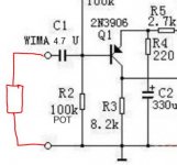
Where would I connect the 470K, at the input side or the side away from the input?
As Andrew says... like this. There should be no measurable dc after doing this.
Attachments
Thanks Guys,
I'll install the 470K resistor and see how that looks and sounds. If it is necessary I can't understand why Hood didn't implement it.
I will try the square waves test when I get it all put back together.
Thanks again
I'll install the 470K resistor and see how that looks and sounds. If it is necessary I can't understand why Hood didn't implement it.
I will try the square waves test when I get it all put back together.
Thanks again
Thanks Guys,
I'll install the 470K resistor and see how that looks and sounds. If it is necessary I can't understand why Hood didn't implement it.
I will try the square waves test when I get it all put back together.
Thanks again
Two reasons, one is that technically, the equipment feeding the power amp should be ground referenced which would perform the same function as the 470K. The other reason is that the design was presented in what was back then then the "top or professional" electronics publication of the day, and such matters would be left to the individual to implement.
The supply I am using is ground referenced. The DC ground is connected to the case which is earth grounded. The PS output has zero AC ripple. I realize that in reality, there is a + and - rail and no ground but the - rail is connected to earth ground. I don't mind adding the 470K resistor. The truth is, this was mainly an experiment to see if the server supply could be used for audio. I thought it would work well for class A because of the high amp output. There is no sag at all since it is regulated. The JLH seemed like a good candidate since it is single polarity. It works fine but has some shortfalls it seems. The sound is just OK, nothing memorable.
Once the Source is connected to the Receiver, the grounding resistor does nothing any good. It is simply an extra "load" that the Source must drive.
The main benefit of the grounding resistor is when one end or the other of the interconnect is disconnected. It prevents a DC voltage building up on the disconnected In/Out. This grounding resistor should be fitted at both the Source Output and at the Receiver Input.
Most users will not ever "hot plug" their interconnects. In this normal operation the grounding resistor/s will have virtually nothing to do (just that extra loading).
If one is ever tempted to "hot plug" switched on gear then the grounding resistor is mandatory at BOTH input and output to help attenuate the "pulse" that can destroy speakers on connecting a leaky capacitor to a "live" input.
Once the Source is connected to the Receiver, the grounding resistor does nothing any good. It is simply an extra "load" that the Source must drive.
Unless its a source with an unterminated output cap. Then you have to caps in series and the real possibility of one acquiring a reverse bias. I suspect that could be a common scenario years ago with diy gear.
Would that reverse bias do any harm to the signal?Unless its a source with an unterminated output cap. Then you have to caps in series and the real possibility of one acquiring a reverse bias. I suspect that could be a common scenario years ago with diy gear.
The value of the voltage bias will be determined by the leakage ratio of the caps and the voltages either side of the caps. The bias would probably be fairly small.
The sound is just OK, nothing memorable.
To some degree the JLH shouldn't be "memorable": it's a very neutral amplifier.
What should be noticeable is that you won't have a desire to turn it off. In my experience it is "adjective free" - it just plays music.
To some degree the JLH shouldn't be "memorable": it's a very neutral amplifier.
What should be noticeable is that you won't have a desire to turn it off. In my experience it is "adjective free" - it just plays music.
I can agree that it won't make you want to turn it off, but for me it left me wanting. I missed the open soundstage. The lacking bigness of a well recorded double bass. I would classify it as low-fi. Pleasant enough to listen to if you don't have something better but for me, not worth the heat.
Hi, I found this Kit on ebay, it had no instructions/diagram at all, but cost me nothing! about £14 its a
JLH 1969 Mini Amplifier by "La Mer"
Does anyone know which schematic would fit this version ? looking at the board there is a part on the PCB "RCL" and "JP-1", Im not sure what to put there I presume JP-1 is to be jumpered!

C2 and C3, look like they would be the larger Orange capacitors
C5 and C4, I have 250uf caps and also 270uf caps came in the bag, so I presume I can use either but ill use the 250 I think.
So that just leaves RCL ?

Any help apreciated! 🙂
JLH 1969 Mini Amplifier by "La Mer"
Does anyone know which schematic would fit this version ? looking at the board there is a part on the PCB "RCL" and "JP-1", Im not sure what to put there I presume JP-1 is to be jumpered!
C2 and C3, look like they would be the larger Orange capacitors
C5 and C4, I have 250uf caps and also 270uf caps came in the bag, so I presume I can use either but ill use the 250 I think.
So that just leaves RCL ?
Any help apreciated! 🙂
You should be able to reverse engineer back from the PCB to a schematic.
Then compare your sch to the original JLH and clones.
Then compare your sch to the original JLH and clones.
Thanks AndrewT
Iv'e found everything apart from what goes in place of RCL, there was no inductor in the package so. Im guessing to put a resistor there, none of the diagrams Iv'e found compare to this circuit!
the RCL connects to one pin of the Bias Adjuster Variable resistor.
Iv'e found everything apart from what goes in place of RCL, there was no inductor in the package so. Im guessing to put a resistor there, none of the diagrams Iv'e found compare to this circuit!
the RCL connects to one pin of the Bias Adjuster Variable resistor.
In my experience it is "adjective free" - it just plays music.
Now that is an accurate description of a good amp if ever I heard one.
Last edited:
supply rail voltage
Hi all, I build jhl class a with 4x MJ15003 for chanel, my tranfo: 2x22.5 VAC, output voltage from regulator: 28V-0-28V , what do you think? if the voltage is so high? must i rebuild tranfo? any ideas ???thanks
Hi all, I build jhl class a with 4x MJ15003 for chanel, my tranfo: 2x22.5 VAC, output voltage from regulator: 28V-0-28V , what do you think? if the voltage is so high? must i rebuild tranfo? any ideas ???thanks
Member
Joined 2009
Paid Member
Thank Bigun, my heatsink is 0.6311 deg C/ W without fan, alumium 150x300x4mm dimension if is OK? anybody have some experience???
- Home
- Amplifiers
- Solid State
- JLH 10 Watt class A amplifier