Part properties
 Yes, thanks Jeff, that should be my second thought, i will test possibilities to find a solution for my use.
 ")
HTML:
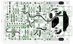
..... go into the parts properties and select Attached Pattern and change it there. As long as the RefDes and the net names haven't changed everything will remain when you renew the layout.Few months ago i get from Jeff the complete set of boards to build an NS amplifier. The end result you can see in the pictures.
Many thanks for Jeff and Valery for the great advice and support in the process of building. I found working with SMD component easier than with THT.
I listened to VFA and CFA IPSs till now and i can assure you that both sound stunning. The entire sound give you a sense of big and detail in the same time. I don`t know what you will ask more for an amplifier to sound.
The best amp that i build till now, a no compromise design.
An externally hosted image should be here but it was not working when we last tested it.
An externally hosted image should be here but it was not working when we last tested it.
An externally hosted image should be here but it was not working when we last tested it.
An externally hosted image should be here but it was not working when we last tested it.
An externally hosted image should be here but it was not working when we last tested it.
An externally hosted image should be here but it was not working when we last tested it.
An externally hosted image should be here but it was not working when we last tested it.
An externally hosted image should be here but it was not working when we last tested it.
An externally hosted image should be here but it was not working when we last tested it.
An externally hosted image should be here but it was not working when we last tested it.
what about the exicon lateral mosfets? I believe they are still producing.Because Hitachi were the only one to develop high power Lateral mosFETs and they sold off the company to become Renesas.
All the others are either licensed by Renesas, or actually made in the same factory.
Go back to the earthquake that took out a large part of South Japan. The one factory manufacturing Laterals needed a couple of years to get production running again.
The whole world supply dried up. There was NOTHING available from anywhere else.
It seems the one factory makes all the big Laterals.
And that probably explains why all the datasheets are nearly identical.
Minor power and current variations depending on how they attach the die to the copper backplate.
And that probably explains why all the datasheets are nearly identical. Minor power and current variations depending on how they attach the die to the copper backplate.
The exicon Laterals seem to be near identical to all the other big power Laterals, look at the datasheets if you don't believe me.what about the exicon lateral mosfets? I believe they are still producing.
Aureaux high-quality no-global-loop headphone amp design
Hi All,
Being focused on low-loop-gain / no global loop power amps this year, I have designed a few circuits, utilizing only local feedback loops, maintaining high linearity and wide bandwidth, providing excellent “short” harmonic profiles (only 2-nd and 3-rd harmonics are noticeable) for top quality sound reproduction.
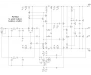
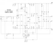
Here is the “younger brother” of those amps – headphone amplifier with current-driven VAS (partially re-using some ideas from Lichtstark front-end), class A output stage and no global feedback loop. Interesting specialty of no-global-loop designs – there must be a sufficient buffer between the VAS and OPS for impedance matching and preventing the OPS’s input impedance modulation from influencing the open-loop front-end’s performance. It's a pity mid-power lateral MOSFETs are not really available these days - perfect devices for the purpose.
Key observations:
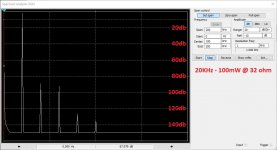
THD20 < 0.003% @ 50mW / < 0.005% @ 100mW (32 ohm load – simulated spectrums).
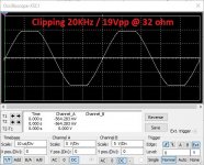
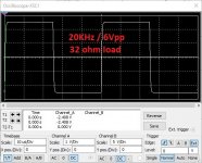
Fast enough step response with no overshoot, clean clipping.
Output HexFETs’ quiescent current is 180…200mA.
Both RCA (unbalanced) and XLR (Balanced) inputs are supported.
I recommend to use some simple soft-start / protection board for keeping the precious headphones safe.
It’s not tested live as yes, I have also got no layout for it right now, although schematic is available in Diptrace. Thoughts, ideas, possible help with layout design and testing – welcome 😉
Cheers,
Valery
P.S. Left schematic shows the IPS/VAS with separate transistors for better view on topology, the right one - same thing, but using the dual pairs.
Hi All,
Being focused on low-loop-gain / no global loop power amps this year, I have designed a few circuits, utilizing only local feedback loops, maintaining high linearity and wide bandwidth, providing excellent “short” harmonic profiles (only 2-nd and 3-rd harmonics are noticeable) for top quality sound reproduction.
Here is the “younger brother” of those amps – headphone amplifier with current-driven VAS (partially re-using some ideas from Lichtstark front-end), class A output stage and no global feedback loop. Interesting specialty of no-global-loop designs – there must be a sufficient buffer between the VAS and OPS for impedance matching and preventing the OPS’s input impedance modulation from influencing the open-loop front-end’s performance. It's a pity mid-power lateral MOSFETs are not really available these days - perfect devices for the purpose.
Key observations:
THD20 < 0.003% @ 50mW / < 0.005% @ 100mW (32 ohm load – simulated spectrums).
Fast enough step response with no overshoot, clean clipping.
Output HexFETs’ quiescent current is 180…200mA.
Both RCA (unbalanced) and XLR (Balanced) inputs are supported.
I recommend to use some simple soft-start / protection board for keeping the precious headphones safe.
It’s not tested live as yes, I have also got no layout for it right now, although schematic is available in Diptrace. Thoughts, ideas, possible help with layout design and testing – welcome 😉
Cheers,
Valery
P.S. Left schematic shows the IPS/VAS with separate transistors for better view on topology, the right one - same thing, but using the dual pairs.
Attachments
-
 Aureaux-sch-00.JPG183.5 KB · Views: 877
 -
 Aureaux-sch-05_Clipping_20KHz.JPG96.2 KB · Views: 215
 -
 Aureaux-sch-04_Square_wave_20KHz.JPG91.7 KB · Views: 459
 -
 Aureaux-sch-03_Spectrum_20K_100mW.JPG132.9 KB · Views: 484
 -
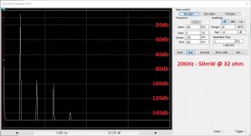 Aureaux-sch-02_Spectrum_20K_50mW.JPG131.2 KB · Views: 732
 -
 Aureaux-sch-01.JPG184.3 KB · Views: 889
Thanks for kind answer.
I have found that way, if i place first parts near like schematic, like your work, it makes it
simpler to view.... placement...traces....lesson learned.
Yes, yes SMD is Future and i collect some informations to work with over last month now.
Libary in Diptrace is good filled with useable parts so i will try that Challange next.....some month
Forgot to mention - voltage gain is set to 10db.
It can be adjusted by changing the value of R21 (i-to-V conversion, lower value -> lower gain and vice versa).
Nice circuit, is the circuit unity gain stable? (since so many headphones will blow you out of the room on 100 mV signal)
Nice circuit, is the circuit unity gain stable? (since so many headphones will blow you out of the room on 100 mV signal)
Hi Daniel,
The whole idea of the circuit is to utilize only the local feedbacks, refusing from global or multi-stage loops. It is unity gain stable by design - no multi-stage loops ensure there are no stability issues. However, for unity gain the circuit can be significantly simplified - you can replace the front-end with a diamond buffer, for example.
However some commercial headphone amplifiers are produced with 2 gain settings (low/high switch), providing the gain of 2.5 (8db) for "low" and 6.5 (16db) for "high". In this circuit, those gain values can be set by the trans-impedance conversion resistor (R21) value:
8db -> R21 = 2.7K
16db -> R21 = 6.8K
I'm showing distortion figures and profiles at 100mW of output power just for showing some "extreme" values - at the normal listening levels, distortion is just negligible - it's comparable to noise level, which is also very low here
I will start a new thread on no-global loop designs in a few days - I see a lot of potential in this area, especially in terms of accurate reproduction of complex multi-tone signals - which the music signals are
Cheers,
Valery
Thanks for kind answer.
I have found that way, if i place first parts near like schematic, like your work, it makes it
simpler to view.... placement...traces....lesson learned.
Yes, yes SMD is Future and i collect some informations to work with over last month now.
Libary in Diptrace is good filled with useable parts so i will try that Challange next.....some month
Yes - Diptrace is well filled with SMD parts - easy to use.
BTW, I'm in Germany, close to Bodensee (Friedrichshafen) till Wednesday
Had a meeting in Frankfurt yesterday, but it's only now I've realized Rheinhessen is actually in that area
Don't you plan to spend some time at the lake during the weekend?
It would be fantastic to have a beer somewhere here
Cheers,
Valery
Germany the best Beer
Germany the best Beer
This kind of statement may potentially start a discussion - people from Belguim may disagree for example
- but yes, it's excellent here for sure Oh what a great offer.
Valery you are Gentleman, thank you.
The Sad is i have to work hole weekend in Restaurant, my only possibility to receive money in a beautiful called "Minijob"(my bad health)- the other side of Germans livestyle.... not to tell about more here.
You know that the German Beer Market is dominated by only 5 big Manufacturers?
I believe only Bayern is very traditionell there.
Val if you can get Beer from Lauingen(ULM/Augsburg)- a little Manufacturer produced a excellent Dunkles Hefeweizen- you should taste it
I have worked as Camion Chaufeur and like also French Kanterbräu Gold Beer from Strassbourg and Wine of corse.
I prefer more the Wine here- more than enaugh....hi....hi....hi.
Wish you a nice Time.
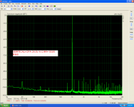
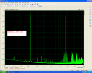
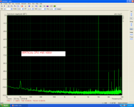
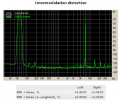
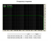
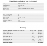
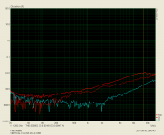
Hi guys ,i want to share a new test for this Vertical CFA as input board and Non Switching as output.
Please have a look.
In the first photo is the sound card loop test as reference.
Power supply +/-50v
74000uf/rail
Idle=40mA/Pair
Please have a look.
In the first photo is the sound card loop test as reference.
Power supply +/-50v
74000uf/rail
Idle=40mA/Pair
Attachments

Last edited:
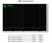
Using RightMark Audio Analyzer, RMAA
Attachments
- Home
- Amplifiers
- Solid State
- Revisiting some "old" ideas from 1970's - IPS, OPS