I've managed to get a through hole version of CDC-VFA-SYMM layed out but I had to enlarge the board and add 14 jumper wires to get it connected. There's a lot of components to this input but as layed out will fit quite nicely on a 3" x 4" standard double sided Slewmaster input board.
Would you have near that many jumpers if you did a 2-layer board?
Thanks...
Would you have near that many jumpers if you did a 2-layer board?
Thanks...
A two layer board wouldn't have any jumpers.
A two layer board wouldn't have any jumpers.
Is it possible that you could do a 2-layer board in the near future once Valery and Still get the bugs(if any) worked out?
I don't etch my own boards and think a 2-layer board is the way to go for most projects. Plus, as you know they're relatively inexpensive if kept under 4" square.
Are you using Sprint or some other software?
Thanks...
Hi Valery,
I haven't done any more with this IPS but something did come to mind. I have 220n in C8 instead of 100n. Could this be part of the issue? I received a bag of 100n caps today so I can change it out if needed. Opinions?
Thanks, Terry
Hi Terry,
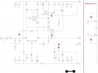
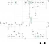
I did some modelling particularly with Slewmaster OPS - it noticeably changes the open loop response. So I have come up with certain compensation scheme re-design (removing, changing and adding some caps) - see attached. It is actually simpler, but providing more control over the system.
The ones that are changed, as well as the one that is added (C21), are marked by the green boxes. The ones removed - by the red X signs.
Please note - it is also recommended to raise the legs of the shunting caps at the input of Slewmaster board - see the right side of the picture.
Please proceed with care (bulb tester, but full rails voltage).
Cheers,
Valery
Attachments
Hi Valery,
I made the changes you suggested and I don't see a lot of change. I am not using the Slewmaster OPS right now, I'm using the Tubsumo OPS. There is no load attached.
I made the changes you suggested and I don't see a lot of change. I am not using the Slewmaster OPS right now, I'm using the Tubsumo OPS. There is no load attached.
Attachments
Last edited:
Hi Terry,
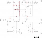
Did a lot of in-depth research and modelling. It appears that the cascoded differential circuit does not cooperate with the LTP's current mirror well, so I did significant simplification of that part of IPS.
Sorry for all this trouble, but you provide a lot of help as I cannot test anything myself at the moment. Good thing - still no trace cutting required")
Attached schematic - what the circuit should look like now. Some parts are removed and jumpered. Can you try this variant with TubSuMo OPS please.
Please note - for TubSuMo, higher VAS current is recommended - 15mA, so R23 = 47R for that purpose. TO-126's will run a bit warmer.
Let me know if more explanation is needed.
Cheers,
Valery
Did a lot of in-depth research and modelling. It appears that the cascoded differential circuit does not cooperate with the LTP's current mirror well, so I did significant simplification of that part of IPS.
Sorry for all this trouble, but you provide a lot of help as I cannot test anything myself at the moment. Good thing - still no trace cutting required
Attached schematic - what the circuit should look like now. Some parts are removed and jumpered. Can you try this variant with TubSuMo OPS please.
Please note - for TubSuMo, higher VAS current is recommended - 15mA, so R23 = 47R for that purpose. TO-126's will run a bit warmer.
Let me know if more explanation is needed.
Cheers,
Valery
Attachments
Hi Terry,
Did a lot of in-depth research and modelling. It appears that the cascoded differential circuit does not cooperate with the LTP's current mirror well, so I did significant simplification of that part of IPS.
Sorry for all this trouble, but you provide a lot of help as I cannot test anything myself at the moment. Good thing - still no trace cutting required
Attached schematic - what the circuit should look like now. Some parts are removed and jumpered. Can you try this variant with TubSuMo OPS please.
Please note - for TubSuMo, higher VAS current is recommended - 15mA, so R23 = 47R for that purpose. TO-126's will run a bit warmer.
Let me know if more explanation is needed.
Cheers,
Valery
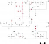
Attached is a revised schematic as I see it. Let me know if I missed anything.
Thanks, Terry
Attachments
Attached is a revised schematic as I see it. Let me know if I missed anything.
Thanks, Terry
Couple of other things - C12, C15, R20 are not required as well.
Also, R8 should be 180R - my mistake (copy/paste again!), it was not too significant when the mirror was there, but now it's much more important for LTP balance.
Cheers,
Valery
Attachments
Couple of other things - C12, C15, R20 are not required as well.
Also, R8 should be 180R - my mistake (copy/paste again!), it was not too significant when the mirror was there, but now it's much more important for LTP balance.
Cheers,
Valery
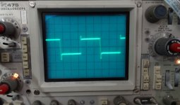
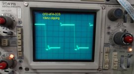
OK I made the changes and tested. With no load it looks great. However, add a load and it stops playing nice instantly. One more thing of note. With no load it clips with less than 1V input. Here are some scope shots. All the square wave shots are with 10vac output.
Attachments
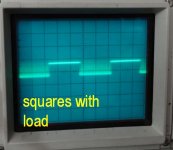
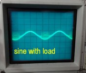
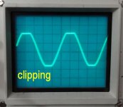
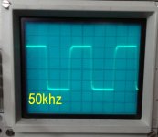
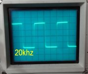
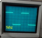
OK I made the changes and tested. With no load it looks great. However, add a load and it stops playing nice instantly. One more thing of note. With no load it clips with less than 1V input. Here are some scope shots. All the square wave shots are with 10vac output.
Hi Terry,
Much better! Looks like a local oscillation in the OPS (negative shoulder). Does the amplitude decrease with the load? This would be strange, as 8R load should not decrease the amplitude that much.
Can we try to put R7, C9 (470R, 100pF) back in place - then test - and after that R20, C15 (47R, 150pF) back in place - and then test.
It will make the loop response close to ideal.
If the oscillation is still there - please try to increase R23 - like 68R, then 100R - re-biasing each time.
Many thanks,
Valery
Sorry, I don't know what you mean by amplitude. Once I attach the load I can't raise the input any without seeing that oscillation on the negative shoulder.
I have a Dr appointment this morning but will try to get the tests done before that. You are like 8 hours ahead of me so we don't have a very large window to work in.
Blessings, Terry
I have a Dr appointment this morning but will try to get the tests done before that. You are like 8 hours ahead of me so we don't have a very large window to work in.
Blessings, Terry
Hi Terry,
Much better! Looks like a local oscillation in the OPS (negative shoulder). Does the amplitude decrease with the load? This would be strange, as 8R load should not decrease the amplitude that much.
Can we try to put R7, C9 (470R, 100pF) back in place - then test - and after that R20, C15 (47R, 150pF) back in place - and then test.
It will make the loop response close to ideal.
If the oscillation is still there - please try to increase R23 - like 68R, then 100R - re-biasing each time.
Many thanks,
Valery
Hi Valery,
OK, I tried the R7, C9 first. A slight improvement. Then R20, C15, no change. Then changed R23. No change except I needed to adjust the bais.
A couple thing of note in case in might help. The lowest I can get the offset with full travel of the pot is +124mV. I can increase it but not lower than that. With everything set as is I have 630mV across R23 (100R). PD+ = +834mV and ND- = -340mV
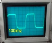
It's a shame this is doing this because without a load, these are some of the crispest square waves I've seen from any amp I've built. I may try the Mini Slew to see if I'm getting the same issues if I can bias it low enough.
Blessings, Terry
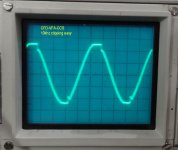
I hooked up the Mini Slew. I set it to 76mA per rail, (the lowest it will go. I see some type of signal with the input shorted and no load. If I play a square wave through it I see a thick line on both positive and negative shoulders but of course I see a thick line with no signal. Adding a load doesn't seem to change much but raises the bias to about 80mA. I'm attaching scope shots of what I see with the input shorted. I had to increase the TIME/DIV. I am including a shot of that too as I don't know how to use that feature other than turn the knob.
Attachments
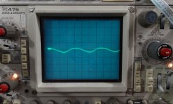
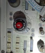
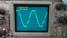
The input is shorted. This is not there with another IPS. I just hooked up the CFA-XH IPS and it looks perfect. That ripple is coming from this IPS.
Terry, thanks a lot - very useful. It slightly oscillates - not violently, but it's there.
I will think a little bit. The thing looks very promising, but requires particularly careful compensation.
It it 0.1uS setting? The value between the black marks?
Then it oscillates at around 2.85MHz...
Last edited:
- Home
- Amplifiers
- Solid State
- Revisiting some "old" ideas from 1970's - IPS, OPS