I'd love to see how compact an SMD version of this would be.
I designed these IPS's to use less current than some op-amps.
Hellraiser is 17mA per rail with the servo.
Son of badger is less than 15mA. NO heatsinks.
OS
I designed these IPS's to use less current than some op-amps.
Hellraiser is 17mA per rail with the servo.
Son of badger is less than 15mA. NO heatsinks.
OS
I was planning to do SMT and through hole for inputs. The through hole version is what's giving me the space issues. The output stage will be all through hole.
We need to find some different through hole input transistors. BC560s aren't available any more.
We need to find some different through hole input transistors. BC560s aren't available any more.
NPO 1206 caps and 1206 thin film resistors make for a tiny board! We've had good luck testing FTZ696/795 instead of KSA1381/C3503 to make the whole input SMT.
Also , on the Hellraiser ....
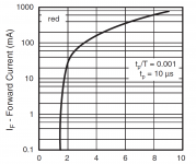
Q5/7 CCS's - depending on what RED LED you have and the real world properties of the semi's , the target
is 1.5ma current. This will set the IPS to optimum so that you can trim VAS I (R17) to 4.25ma.
Newer RED LED's have as much as 1.8 - 1.9 Vf old dim red's GaAs have 1.6 - 1.7 Vf , CCS Re has to increase
for newer red's.
OS
I found a nice red LED, with very low internal impedance, even with low current. It has approx. 1,7V Vf at 2mA, and approx.1,65V at 0,5mA.
Sajti
Attachments
I have a couple versions of the new Honeybadger half done. The UMS layout isn't great for layouts on larger amps! It looks like it'll need a plug in input board just to allow enough space to fit everything. A two row output stage like the Slewmaster used looks a lot better than the previous single row layout.
I just emailed Jason , could we have something to show ? Please include
all (of us) in the layout.
That is surprising about space , the current Badger PCB is so spread out.
I also needs a VAS HS. This design could be much more dense. 3 pair
outputs could even be driven by a pair of to3p drivers face to face with
the driver Vbe in-between to-3p's or to-220's (below - HK680).
A small plate or PCB mounted HS with Q103/107/108 would be nice.
The reason for the Slewmaster large driver plate is overkill factor (for EvanC
"manly" monster amps.
OS
Attachments
https://www.mouser.com/datasheet/2/408/TTA004B_datasheet_en_20170109-1102732.pdf
I'll go to Mouser - yep 550/560 - obsolete
They still have taiwan semi BC546/556 (new product) !
And On semi 546/556
Any grade Vceo would work , both team red/blue amps only expose
the devices to 20V Vceo.
ZTX 553/563 seem to be a good replacement for Ksa/c 992/1845's
Mouser is out of 1845's !!! 120,000 on order.
Through - hole is getting sparse , only 54 results for higher voltage to-92's.
Edit and the TTC/A 004b should be perfect TO-126 replacements for rails under 70V.
https://www.mouser.com/datasheet/2/408/TTA004B_datasheet_en_20170109-1102732.pdf
OS
I was planning to do SMT and through hole for inputs. The through hole version is what's giving me the space issues. The output stage will be all through hole.
We need to find some different through hole input transistors. BC560s aren't available any more.
I'll go to Mouser - yep 550/560 - obsolete
They still have taiwan semi BC546/556 (new product) !
And On semi 546/556
Any grade Vceo would work , both team red/blue amps only expose
the devices to 20V Vceo.
ZTX 553/563 seem to be a good replacement for Ksa/c 992/1845's
Mouser is out of 1845's !!! 120,000 on order.
Through - hole is getting sparse , only 54 results for higher voltage to-92's.
Edit and the TTC/A 004b should be perfect TO-126 replacements for rails under 70V.
https://www.mouser.com/datasheet/2/408/TTA004B_datasheet_en_20170109-1102732.pdf
OS
Last edited:
Check out Onsemi BC549CTA/559CTA! They are nice devices, if 550C/560C is missing...
Edit: Bad luck as BC559CTA is out of stock. Anyway 549BTA/559BTA have in stock, if the lower hfe range is no problem....
Sajti
Edit: Bad luck as BC559CTA is out of stock. Anyway 549BTA/559BTA have in stock, if the lower hfe range is no problem....
Sajti
Last edited:
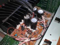
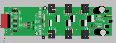
I don't have all of the right 3D models loaded yet. The Slewmaster style layout still needs the servo, servo regulators and the cap multipliers placed. It might fit but it'll be ugly! The screw holes limit the board to around 2 3/4" wide so it's pretty slim.
The screw hole locations aren't playing out well in the Badger version. If we want to screw off the driver heat sink they need to be in the middle of the board killing a lot of space.
Now that you have some final designs published I'll dig a little deeper and see what I can come up with.
The screw hole locations aren't playing out well in the Badger version. If we want to screw off the driver heat sink they need to be in the middle of the board killing a lot of space.
Now that you have some final designs published I'll dig a little deeper and see what I can come up with.
Attachments
I was looking at BC549/559. They look pretty similar to the BC550/560 and easily available for now.
I stocked up on all of the through hole components a few years ago but switched to SMT so I still have lots to work with. Still hoarding Sanken MT200s too.
I stocked up on all of the through hole components a few years ago but switched to SMT so I still have lots to work with. Still hoarding Sanken MT200s too.
I don't have all of the right 3D models loaded yet. The Slewmaster style layout still needs the servo, servo regulators and the cap multipliers placed. It might fit but it'll be ugly! The screw holes limit the board to around 2 3/4" wide so it's pretty slim.
The screw hole locations aren't playing out well in the Badger version. If we want to screw off the driver heat sink they need to be in the middle of the board killing a lot of space.
Now that you have some final designs published I'll dig a little deeper and see what I can come up with.
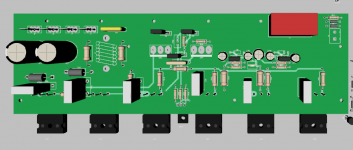
Here is a good template for power layout. One could do what they do with
the wires by using fat traces on the double sided board (below). Onboard
decoupling caps just have to be 470u/ 80V. Most use the DIYA store big cap bank PCB.
Caps and power traces in the middle.
Actually , twisting those wires together under the board is a killer idea .
Rail ripple would be totally cancelled.
OS
Attachments

Jeff, please keep the IPS separation. 😉
Maybe I could convince Jason to standardize between The store's Badger and
The slewmaster.
I think both the builders and store could have a lot more fun (and profit).
The power/EF3/ protection could be on main board , either IPS through- hole or
SMD kits of the builders choosing. This would feed the audiophile yearning
for listening to a classic Nikko or HK ... or leach amp on a modern output
stage.
Another idea is to even have instructions to use a dummy load pretest of the OPS
WITHOUT the IPS. I did this when I had a slewmaster - never any smoke !!!
OS
Last edited:
The wire routing is a great idea! Having power connections at opposite sides of the boards is begging to have the wires all over the place. The tie wrap holes fix that here though.
I try to bring both power leads to the board close together forcing the builder to run the power leads fairly close together. I like to run the two power planes on top of each other so they cancel their emissions too.
I try to bring both power leads to the board close together forcing the builder to run the power leads fairly close together. I like to run the two power planes on top of each other so they cancel their emissions too.
If they were to work in a 5 pair pattern with enough space for a 10mm wide board I'd use their pattern for all of my layouts.
Check out Onsemi BC549CTA/559CTA! They are nice devices, if 550C/560C is missing...
Edit: Bad luck as BC559CTA is out of stock. Anyway 549BTA/559BTA have in stock, if the lower hfe range is no problem....
Sajti
I'm very curious about the quality of various BC5xx from the remaining manufacturers. I'm hesitant to trust them because I know that quasi-saturation and Early voltage and base resistance can be totally different between manufacturers. Maybe someone can test them with a DCA Pro.
Here is a good template for power layout. One could do what they do with
the wires by using fat traces on the double sided board (below). Onboard
decoupling caps just have to be 470u/ 80V. Most use the DIYA store big cap bank PCB.
Caps and power traces in the middle.
Actually , twisting those wires together under the board is a killer idea .
Rail ripple would be totally cancelled.
OS
I’m trying to visualise and understand this. Sorry if I don’t get it.
The twisted wires will cancel the ripple…. OK I see that.
However since the audio signal is asymmetrical, not a sine wave, the power demand on one wire could be more than the other (using positive and negative rails).
Can the transient demand in one wire cause induced “interference” into the other wire or am I looking at it in the wrong way?
Ripple voltage on the supplies will be almost totally unaffected. The main thing is reducing the physical loop area of the supply currents. The area of the current loop determines the amount of magnetic coupling to other traces.
On some boards the loop area is practically the whole size of the PCB because the rails are routed on the outer edge of the board.
On some boards the loop area is practically the whole size of the PCB because the rails are routed on the outer edge of the board.
I just emailed Jason , could we have something to show ? Please include
all (of us) in the layout.
That is surprising about space , the current Badger PCB is so spread out.
I also needs a VAS HS. This design could be much more dense. 3 pair
outputs could even be driven by a pair of to3p drivers face to face with
the driver Vbe in-between to-3p's or to-220's (below - HK680).
A small plate or PCB mounted HS with Q103/107/108 would be nice.
The reason for the Slewmaster large driver plate is overkill factor (for EvanC
"manly" monster amps.
OS
I've always enjoyed using these heatsinks for TO-126, TO-220, and TO-247 which would also work for TO-3P.
I like them because they solder to the pcb with pins and keep your transistors secure and from flapping in the breeze.
Here is the Digikey TO-126/TO-220 1.5" tall part number HS346-ND
Attachments
- Home
- Amplifiers
- Solid State
- Slewmaster - CFA vs. VFA "Rumble"