trimmer range ....
With the values on the posted Schema , (below) is the VAS current range.
With your (1K trimmers) .... your range should be 2-8ma VAS current (or more)
with 1K R13/16 !! That is why I added them - no other values need to be
changed with such a range on the CCS's !
PS - also with the trimmers .... read the servo output voltage , by setting one
a little different from the other ... the servo voltage will drop (<1V) , as it is not
compensating for as much of a input pair imbalance.
OS
Attachments
Last edited:
There they are. Pirate away 😀 .
OS
Thanks. I'll get a look at them later tonight.
Ok OS problem has already been solved.Sorry for this.With the values on the posted Schema , (below) is the VAS current range.
With your (1K trimmers) .... your range should be 2-8ma VAS current (or more)
with 1K R13/16 !! That is why I added them - no other values need to be
changed with such a range on the CCS's !
PS - also with the trimmers .... read the servo output voltage , by setting one
a little different from the other ... the servo voltage will drop (<1V) , as it is not
compensating for as much of a input pair imbalance.
OS
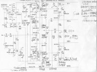
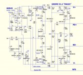
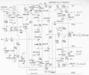
Here is shematic with measurments
Attachments

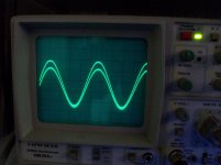
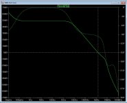
Inp and out signal .1KHz-100KHz
Attachments
Last edited:
I see you have 1.266VOk OS problem has already been solved.Sorry for this.
Here is shematic with measurments
at servo output ... like I said , try to manually offset one of the IP pair CSS's
to see if you can reduce the servo voltage.
The servo correction voltage is the "window" to see what kind of input
pair imbalance pre-exists. Trimmer tweaks can reduce this. The gnome is
the best of the current DIYA CFA's as far as "fine tuning" the IP stage.
(servo + trimmers) 😎
Ok OS, i can try this tomorrow morning.I see you have 1.266V
at servo output ... like I said , try to manually offset one of the IP pair CSS's
to see if you can reduce the servo voltage.
The servo correction voltage is the "window" to see what kind of input
pair imbalance pre-exists. Trimmer tweaks can reduce this. The gnome is
the best of the current DIYA CFA's as far as "fine tuning" the IP stage.
(servo + trimmers) 😎
keep in mind please that i have matched nothing!😉
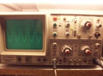
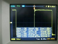
I must mention that from a quick test, i see that some instability appears . Square wave test
Last edited:
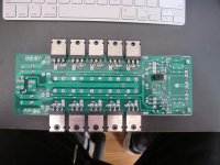
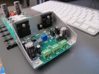
Almost ready for moving electrons...
A few pics to show an almost fully completed board.
One question OS, connecting G2 points - what is your vision for that? A wire under the board perhaps?
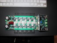
A few pics to show an almost fully completed board.
One question OS, connecting G2 points - what is your vision for that? A wire under the board perhaps?
Attachments


Jason,
What is the distance from the outside to the outside of the output devices? Maximum width is what I am looking for. That is a nice little bracket you made for the heat sink.
What is the distance from the outside to the outside of the output devices? Maximum width is what I am looking for. That is a nice little bracket you made for the heat sink.
Jason, excellent high quality build! Congratulations!
Pls share the results after power-on - very interesting
Pls share the results after power-on - very interesting
A few pics to show an almost fully completed board.
One question OS, connecting G2 points - what is your vision for that? A wire under the board perhaps?
That is the Real THING ... MAN ! 😱
G2 is meant for under the board. A couple dabs of glue to keep it over
near one of the rails. It is the "clean ground".
PS - more exactly (anally) , follow the negative decoupling trace back
to G2. No massive currents there , like near the OP trace(s) or main inductor .
OS
Jason,
What is the distance from the outside to the outside of the output devices? Maximum width is what I am looking for. That is a nice little bracket you made for the heat sink.
4-1/2" Thanks. The bracket needs a litle clean-up, but something like that will support the devices well.
Ok OS, i can try this tomorrow morning.
keep in mind please that i have matched nothing!😉
I must mention that from a quick test, i see that some instability appears . Square wave test
I am 😱😱 , "If it's not broke , don't fix it ! "
(below 1) is the "fix" ...
Too low of a value for R13/16 and R7/8 reduced phase margin just enough
to create overshoot. Lower current feedback resistor values also help (1.5k/56K for R18/17).
Increasing Hawksford LED current closer to the V1.2 (R22-47K) is also best , trimmers can be re-adjusted for optimum 4.5-5ma VAS I.
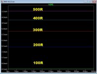
Resulting CLG bode is nearly the V1.2 (below 2).
PS- the servo change had no effect (ran the same inverting or non inv.).
ALL MY FAULT. 🙁 Sorry !
Edit R21/23 (VAS shunt) can be 220-330K , resulting in 52 -48db LF gain.
OS
Attachments
Last edited:
Jason, excellent high quality build! Congratulations!
Pls share the results after power-on - very interesting
I plan on 'dummy testing' the OPS first, but I need to cook up an IPS for a real test. Only question is will it be a 'Spooky Leach' or the IPS formerly known as 'GoNAD' (I liked that better, but hey, go with what pleases the masses).
The film caps you used instead of 22u lytics will resonate madly. I suggest that anyone should build it with the lytics first, listen to it that way, then ADD film decoupling across the lytics. You need the lytics to provide some damping; the larger the film cap, the larger the lytic should be.
He has lots of cheap, better choices - 10 each mouser and digikey- 8mm/ 3.5mm LS 47u !! @ 100V caps to choose from.
They are making some real compact electro's these days !
56u@100V is the largest 8mm/3.5LS ...
UHE2A560MPD Nichicon | Mouser
PS - I observed some former "guru amps" ... (syn08's YAP amp) - just 47-100u per OP (no film).
OS
They are making some real compact electro's these days !
56u@100V is the largest 8mm/3.5LS ...
UHE2A560MPD Nichicon | Mouser
PS - I observed some former "guru amps" ... (syn08's YAP amp) - just 47-100u per OP (no film).
OS
Last edited:
Ack, I put in film 'cause OS suggested it would likely be better. I have a pile of 10µF@100V, would that be a better choice or should I order something bigger?
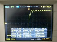
Measurments after updates.
The instability remain.
Amplifier oscillates after clipping also, (sinusoidal wave test)
I measure 2mv A.C on out even when input is sorted but can't hear any noise from speaker.
The instability remain.
Amplifier oscillates after clipping also, (sinusoidal wave test)
I measure 2mv A.C on out even when input is sorted but can't hear any noise from speaker.
Attachments
Last edited:
- Home
- Amplifiers
- Solid State
- Slewmaster - CFA vs. VFA "Rumble"