Hi Dave S
Your setup is picking up so much 50Hz line frequency noise that it clouds the harmonic profile of the 1KHz fundamental....if you fix that you could visually see more easily the real THD profile for this amp... however you have the numbers in the table.
Fab
Your setup is picking up so much 50Hz line frequency noise that it clouds the harmonic profile of the 1KHz fundamental....if you fix that you could visually see more easily the real THD profile for this amp... however you have the numbers in the table.
Fab
Last edited:
Member
Joined 2009
Paid Member
Here's a follow up on my bias issue gentleman. As previously stated, one board operated expectantly, the other was recalcitrant. The second board had a problem with an excessive current draw on the V+ rail, hogging 10 times more current (100 Ma opposed to 10 Ma) when tested at a low operating supply of +/- 20V. I did find a shorted resistor at R36 which measured 2R instead of 100K. I did not see any solder bridges. When replaced, the rail current draw was now equal and no longer excessive. Problem solved? No! Unhappily, I now find that the offset and bias pots have no effect whatsoever. In other words, the offset stays at 0 and rotating VR1 makes no difference. Similarly VR2 has only the slightest degree of affect, and I cannot get above 1.50mv. I have some hunches as to where the problem may be, but rather that do a trial and error replacement of parts where knowledge is at a paucity, I draw upon you once again gentleman to pick your collective brains. Though, it may appear that this has been a frustrating experience for me, I do not see it that way. I have dealt with delayed gratification throughout my life, and know that persistence with will be rewarded. Besides, much of the fun of doing these projects is to learn from guys like you. Before I am done I will have learned a heck of a lot about amplifier circuitry than if I had not encountered any problems. Mistakes are forgivable (I hope!) if one learns.
Stan
Stan
Member
Joined 2009
Paid Member
Hi SC, without looking at the schematic my initial reaction is to check over the board for any other similar errors to the one you discovered and then look at the circuit and think if the error you just fixed could’ve caused some damage to the existing components (such as exceeding voltage ratings and or current ratings) and if there are some simple tests you could perform with a multimeter to check them ?
By the way I fully agree with your philosophy in that a few challenges along the way can add to the pleasure of the win at the end
By the way I fully agree with your philosophy in that a few challenges along the way can add to the pleasure of the win at the end
Hi Dave S
Your setup is picking up so much 50Hz line frequency noise that it clouds the harmonic profile of the 1KHz fundamental....if you fix that you could visually see more easily the real THD profile for this amp... however you have the numbers in the table.
Fab
If it is pickup, I am at a loss as to why the Mooly amp is 40dB better with exactly the same measurement technique.
I guess one possible explanation is that it is due to the TGM8 being in a case that is not earthed (the donor amp has a 2 wire cable). I will repeat with an earthed case/chassis.
Last edited:
I am just saying that something is wrong because so much line noise will be heard for sure In your speakers. So if your setup is good than your amp connections are not...
Otherwise I suspect your frequency generator letting its own 50 Hz line to pass and reaching the input of your amp...
I just made my own generator and neglected to invest in a lower noise isolated psu and I have about -100db 60 Hz for 1Wrms on the thd spectrum..I use the same software as you do.
Fab
Last edited:
Here's a follow up on my bias issue gentleman. As previously stated, one board operated expectantly, the other was recalcitrant. The second board had a problem with an excessive current draw on the V+ rail, hogging 10 times more current (100 Ma opposed to 10 Ma) when tested at a low operating supply of +/- 20V. I did find a shorted resistor at R36 which measured 2R instead of 100K. I did not see any solder bridges. When replaced, the rail current draw was now equal and no longer excessive. Problem solved? No! Unhappily, I now find that the offset and bias pots have no effect whatsoever. In other words, the offset stays at 0 and rotating VR1 makes no difference. Similarly VR2 has only the slightest degree of affect, and I cannot get above 1.50mv. I have some hunches as to where the problem may be, but rather that do a trial and error replacement of parts where knowledge is at a paucity, I draw upon you once again gentleman to pick your collective brains. Though, it may appear that this has been a frustrating experience for me, I do not see it that way. I have dealt with delayed gratification throughout my life, and know that persistence with will be rewarded. Besides, much of the fun of doing these projects is to learn from guys like you. Before I am done I will have learned a heck of a lot about amplifier circuitry than if I had not encountered any problems. Mistakes are forgivable (I hope!) if one learns.
Stan
Re your dc output reading of 0v are you measuring from the output in series before the protection circuit or where it exits to the speaker terminals.
I am just saying that something is wrong because so much line noise will be heard for sure In your speakers. So if your setup is good than your amp connections are not...
Otherwise I suspect your frequency generator letting its own 50 Hz line to pass and reaching the input of your amp...
I just made my own generator and neglected to invest in a lower noise isolated psu and I have about -100db 60 Hz for 1Wrms on the thd spectrum..I use the same software as you do.
Fab
I think you are right. The charging pulses should be at 100Hz, so the 50Hz must be pickup.
I will have another go and try to find out what is going on.
Yes, Gareth, I have looked upstream from the point of infraction and followed the current path to determined if other susceptible components may have been injured. As you know R36 sources current to the base of Q15 (replaced) and collectors of Q12 and Q13 (also replaced). After R36 was replaced, the protection circuit appears to work, as the green LED comes on and stays on. However, the red LED does not flicker as would be expected to occur from the transient DC at the output before adequate bias kicks in. This observation correlates with the lack of any measured DC upon turn on. Everything stays dead, nadda. BTW, Mjona, the DC offset is being measured between ground and R30, not at the speaker output. Following the circuit further back brings us to the output BJT, mosfet and the driver, as you know. I have tested the output devices several times and I will retest them again before considering a swap. After that, I'm not sure. Perhaps playing the Q5 and 6? Q1 seems an unlikely offender. Head scratching? Yes! Have I killed Kitty? No! So...where is my bias?
Yes, Gareth, I have looked upstream from the point of infraction and followed the current path to determined if other susceptible components may have been injured. As you know R36 sources current to the base of Q15 (replaced) and collectors of Q12 and Q13 (also replaced). After R36 was replaced, the protection circuit appears to work, as the green LED comes on and stays on. However, the red LED does not flicker as would be expected to occur from the transient DC at the output before adequate bias kicks in. This observation correlates with the lack of any measured DC upon turn on. Everything stays dead, nadda. BTW, Mjona, the DC offset is being measured between ground and R30, not at the speaker output. Following the circuit further back brings us to the output BJT, mosfet and the driver, as you know. I have tested the output devices several times and I will retest them again before considering a swap. After that, I'm not sure. Perhaps playing the Q5 and 6? Q1 seems an unlikely offender. Head scratching? Yes! Have I killed Kitty? No! So...where is my bias?
Measure the voltage across the collector to emitter of Q5 to see if you can alter this so the voltage can be set to 1.2 volts. The base emitter voltages for the driver transistors and the output ones should have roughly 0.6volt across them.
Iansmusical, see post #949 for top and bottom images of the pcb that I made to help with building the pcb. I printed these out to use to locate and place parts.
George
Thanks George and Bigun for your input. I was also thinking to do that, completely belt and braces approach
") On Linux I've used Gerbv to view the board files that are in this thread and it works very well.
On Linux I've used Gerbv to view the board files that are in this thread and it works very well.On the subject of SMD soldering how did everyone approach it? I was thinking of either tinning a pad and then placing the component or using a syringe with solder paste (recommendation?) on each pad, placing the component and heating with the soldering iron.
Many thanks.
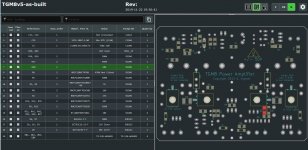
Assembling the boards using Kicad
I highly recommend Kicad, not just for layout but for kitting and assembly. You need to download and install the Interactive HTML BOM plugin. See here YouTube As you can see the BOM tool allows you to locate each component on the BOM. It will split your BOM into top and bottom sides so you can assemble one side at a time easily and mark off each component as you go. I downloaded Gareth’s design files from post 404 and imported the Eagle project into Kicad. I did however have to manually copy the published TGM8 BOM (word doc) into Kicad, but it was worth it.
I highly recommend Kicad, not just for layout but for kitting and assembly. You need to download and install the Interactive HTML BOM plugin. See here YouTube As you can see the BOM tool allows you to locate each component on the BOM. It will split your BOM into top and bottom sides so you can assemble one side at a time easily and mark off each component as you go. I downloaded Gareth’s design files from post 404 and imported the Eagle project into Kicad. I did however have to manually copy the published TGM8 BOM (word doc) into Kicad, but it was worth it.
Attachments
Member
Joined 2009
Paid Member
On the subject of SMD soldering how did everyone approach it? I was thinking of either tinning a pad and then placing the component or using a syringe with solder paste (recommendation?) on each pad, placing the component and heating with the soldering iron.
Many thanks.
i’m no expert but what works for me is the following. I do not pretin the pads because this seems to prevent the parts from sitting flat probably because I’m not doing that correctly so I simply avoid doing any pretinning, especially as the PCB is pretinned to some extent.
so I use a pair of plastic tweezers to pick up the small resistors, they weren’t very expensive but they are apparently designed for handling static sensitive parts and they come in a nice black colour. I position the resistor on the board and with a little bit of fresh molten solder on the tip of my iron I solder one end of the resistor and hold it still with the tweezers while the solder cools. then I solder the other end of the resistor and then return to the first end to add more sold or if it is required.
Member
Joined 2009
Paid Member
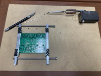
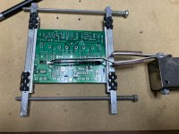
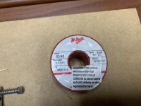
This is how I do surface mount using a few tools that I made. The tweezers are mounted on a steel block so they can pivot up and down. Tension can be adjusted with the screw and lock nut. Grab the part and position it on the pcb. I made a jig to hold the pcb so it can be moved around and flipped over to solder on the other side. I use the solder in the picture and use the largest solder tip that I can so it heats the part quickly and then apply solder. It takes very little solder to attach the part.
Attachments
A note of satisfaction has befallen my ears. It is worth sharing. Alas, I have found it...eureka...music! The failure of the prior channel to attain bias was not the board, but me. As you recall, having replaced a shorted R36 (I still can't reconcile how a resistor can be shorted), the V+ rail voltage drop problem was resolved. However, the bias and offset were not behaving. It turns out that the problem was caused by inadequate bias voltage at Q5, when tested at +/- 24V. I decided to crank it up to 30V, since the excessive current draw on the V+ rail had been resolved. Suddenly, the pots decided to work! You may say, well that should be obvious, based on Dave's prior comment. Well, yes. But my reluctance to trust my instincts and his advice was due to a heuristic bias. With the first board, I was able to adjust the bias when the rails exceeded 20V. So when the second board misbehaved at 24V supply, I wanted to check things out further. So when all seemed in order, so I cranked it up to 30V. Bingo! So, what are the lessons here? The first is that I used a 100R across the fuse holders as the test resistor. Rod Elliot suggested 22R. I wonder if the higher value affected and contributed to the problem, i.e. would using the 22R allow the set up to occur at the lower rails? My second observation: There is enough board to board variation to invalidate certain assumptions (based on specific parameters) which may not be trustworthy. In this case, the power up voltage needed to turn on Q5 in the 2 boards was not the same, but sufficiently different. My third mistake: always trust Dave! So, with the bias working and properly adjusted, I decided to play some music. Silence.... Oh no, not again? Not to worry. Problem solved. Loose connection at the optocoupler. Fixed. On the next build, and I plan to build 6 more for the LxMini plus subs, I will solder the optocoupler earlier in the stuffing process to be sure there is adequate room for my iron to get a good joint in that tight space. My listening impressions will be forthcoming once I wipe the sweat off my face.
One final comment: audio electronics, or for that matter, any electronics hobby, brings together talented, creative and inquisitive individuals, all bound by passion. Over the years, I have found that they are most willing to share their knowledge and help one another. What a great model for all societies to build upon. Thank you all and especially Dave, Gareth, George (great construction tips and jigs) and Mjona.
Stan
Last edited:
always trust Dave!
Stan
Ok, so the next step is that you need to transfer $10,000 to my bank account which will enable me to release your $1,000,000 bonus bond.
On a more serious note, it is just so easy to get stuck in a logic trap with (electronics) fault finding. My method for dealing with this is to have a cup of tea, or sleep on it, or both!
I'm still drinking tea on the 50Hz "pickup" on my measurements earlier in this thread. My other amps measure repeatably lower in the same setup and physical location. I can measure my preamp at lower signal levels (100mV RMS) and get 50Hz "pickup" at -114dB (versus -40dB on the TGM8, which I can drop to -55dB by earthing the chassis).
Sadly I can't visit my pal with his AP test rig due to the CV-19 restrictions, to correlate some measurements.
Member
Joined 2009
Paid Member

I'm still drinking tea on the 50Hz "pickup" on my measurements earlier in this thread. My other amps measure repeatably lower in the same setup and physical location. I can measure my preamp at lower signal levels (100mV RMS) and get 50Hz "pickup" at -114dB (versus -40dB on the TGM8, which I can drop to -55dB by earthing the chassis).
Sadly I can't visit my pal with his AP test rig due to the CV-19 restrictions, to correlate some measurements.
I looked at the photo of your chassis attached to post 1080 and can see the transformers have copper strapping around them (good) but the leads from the secondaries are twisted together albeit loosely. These will be less effective in magnetic field cancellation than if made tight as dreadlocks. The same would apply to the inputs and supplies to the amplifier pcb.
It seems also in the photo that the heat sinks for the modules could be sitting on a painted chassis and being anodised these may not be making good contact to earth.
The earth point for your modules should be close to the point near the common connection of the onboard supply capacitors there should be no connection to the capacitors neutral terminal common other than the respective centre tap.
Other earths should be from a T junction with the above common with the dirtiest earths closest to thereto in order of precedence worst first.
For more on this Andrew Russell aka Bonsai has posted information re this subject. He also runs a website for his project amplifiers.
You are running dual monoblocks in one chassis which with two transformers takes up significant space. If twisting cables more tightly does not work turning the modules 180 so the heatsinks face each other could reduce some cable lengths with maybe a cooling fan and vents for the heat sinks.
Last edited:
- Home
- Amplifiers
- Solid State
- TGM8 - my best amplifier, incredible bass, clear highs, no fatigue (inspired by Rod Elliot P3a)