Member
Joined 2009
Paid Member
FWIW my own implementation uses a single transformer in a relatively small chassis where wiring space is so tight I has to wire it up with the chassis in pieces then squeeze all the parts together and pop in the bolts. On my 15” full range speaker it is plenty quiet enough - so it is possible to get a hum free set up.
I looked at the photo of your chassis attached to post 1080 and can see the transformers have copper strapping around them (good) but the leads from the secondaries are twisted together albeit loosely. These will be less effective in magnetic field cancellation than if made tight as dreadlocks. The same would apply to the inputs and supplies to the amplifier pcb.
It seems also in the photo that the heat sinks for the modules could be sitting on a painted chassis and being anodised these may not be making good contact to earth.
The earth point for your modules should be close to the point near the common connection of the onboard supply capacitors there should be no connection to the capacitors neutral terminal common other than the respective centre tap.
Other earths should be from a T junction with the above common with the dirtiest earths closest to thereto in order of precedence worst first.
For more on this Andrew Russell aka Bonsai has posted information re this subject. He also runs a website for his project amplifiers.
You are running dual monoblocks in one chassis which with two transformers takes up significant space. If twisting cables more tightly does not work turning the modules 180 so the heatsinks face each other could reduce some cable lengths with maybe a cooling fan and vents for the heat sinks.
Excellent points!
The original Rotel RB850 has a 2 wire mains cable. The chassis is not earthed. The amp channels (orignal and TGM8) are floating.
Adding an extra wire from mains earth to chassis brought about a modest reduction in the 50Hz "pickup" as mentioned in my previous post.
I have never found super tight twisting of wires to make much difference - as long as the loop area is minimised.
The case is galvanised steel, only the front panel is anodised. No combination of wires that I tried between various 0V points makes much difference to the results.
I have tried moving an entire amplifier channel: further away (from the transformers) and rotating in all 3 axes. No change!
There is only one power 0V connection the PCB. I might try soldering the transformer CT to the underside of the PCB to avoid the shaared faston terminal that I am currently using. However I'm not convinced that will make much difference, the PCB layout may not be optimal:
The caps charge via the red "route", but the signal 0V is connected via the yellow route. Where the red and yellow routes are shared, common impedance coupling can occur.
Ideally the signal 0V star shoult be tee'ed off away from the connection to the CT (as per Doug Self's recommendations).
Just to clarify; there is no audible hum from this amp. Just some concerns about my measurements, which may or may not be correct.
Also - no criticism intended by any of this!
Last edited:
I think this layout would be more D Self compliant (setting aside all the 0V connections on the lower half of the PCB for the time being):
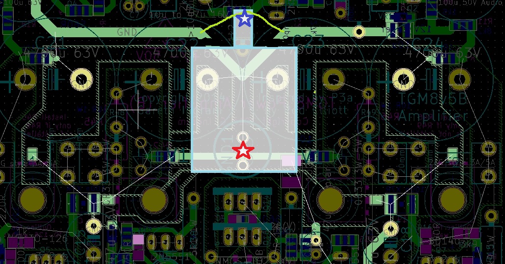
Red = power star 0V
Blue = signal star 0V
Red = power star 0V
Blue = signal star 0V
Last edited:
The machine gave me satisfaction. It produced tranquility. Need I say more? With appreciation, Gareth deserves an amplified 'THANKS' for the many hours of joyful toil put forth to improve an already successful design. Your support and encouragement has made this gift possible for many of us, not to mention, yours truly. The community of supporters have furthered our knowledge and made this a group effort. It's fun. That is why we do this. Not to forget, Robert Pirsig, who gave us the words and his wisdom. It's not just about motorcycles!
Excellent points!
The original Rotel RB850 has a 2 wire mains cable. The chassis is not earthed. The amp channels (orignal and TGM8) are floating.
Adding an extra wire from mains earth to chassis brought about a modest reduction in the 50Hz "pickup" as mentioned in my previous post.
I have never found super tight twisting of wires to make much difference - as long as the loop area is minimised.
The case is galvanised steel, only the front panel is anodised. No combination of wires that I tried between various 0V points makes much difference to the results.
I have tried moving an entire amplifier channel: further away (from the transformers) and rotating in all 3 axes. No change!
There is only one power 0V connection the PCB. I might try soldering the transformer CT to the underside of the PCB to avoid the shaared faston terminal that I am currently using. However I'm not convinced that will make much difference, the PCB layout may not be optimal:

The caps charge via the red "route", but the signal 0V is connected via the yellow route. Where the red and yellow routes are shared, common impedance coupling can occur.
Ideally the signal 0V star shoult be tee'ed off away from the connection to the CT (as per Doug Self's recommendations).
Just to clarify; there is no audible hum from this amp. Just some concerns about my measurements, which may or may not be correct.
Also - no criticism intended by any of this!
If you refer back to page 103 there was some discussion about the reason for adopting the power supply capacitors onboard the pcb after scotty 123 posted images of both sides of those he had just received.
The case for this was placement near the output devices which would help current delivery and promote good bass response.
Then danieltalksbac proposed to reduce the outboard capacitors to serve as local decoupling which would allow him to put some distance from the usual style of power supply he was planning for in his build.
Looking at the pcb those large onboard capacitors are very close to the small signal componentry whilst the whole circuit is floating.
The reason why dreadlock twisting would have no effect with the present set up is that there are charging currents pulsing at 50Hz (or 60Hz in USA) between the supply capacitors zero volt common having nowhere else to go.
The result is a floating magnetic field and such is capable of inducing spurious signals in nearby wires or tracks - the inverting input is capable of amplifying such signals.
If you implement changes as shown in the second image you just posted, I recommend a link between the two ground points with a resistor of 10-22R.
I support your idea of connecting the 0v earth to divert the supply pulse currents to mains earth.
Last edited:
IT'S TIME ONCE AGAIN FOR ME TO PICK SOMEONE'S BRAIN. I am curious as to the proper operation of the protection/delay circuit. On one board, the music comes on when the supply reaches 30V (nominal +/- 40V rails) and shuts down when the rails fall below 30V. I suspect that is the intention of the design and thus the 30V zener is used. However, on the other board, turn on/off occurs at 20V or less. Did I inadvertently use a lower value for the zener, or could there be some other explanation? Is proper protection being afforded? Just curious.
Stan
Stan
Measure voltage on either side of the zener and compare each channel. Easiest way to know for sure
Thanks for your suggestion, bullslitt.
That must be the problem and an obvious way to verify it.
That must be the problem and an obvious way to verify it.
KiCad
Can you share the KiCad files?
I highly recommend Kicad, not just for layout but for kitting and assembly. You need to download and install the Interactive HTML BOM plugin. See here YouTube As you can see the BOM tool allows you to locate each component on the BOM. It will split your BOM into top and bottom sides so you can assemble one side at a time easily and mark off each component as you go. I downloaded Gareth’s design files from post 404 and imported the Eagle project into Kicad. I did however have to manually copy the published TGM8 BOM (word doc) into Kicad, but it was worth it.
Can you share the KiCad files?
Kicad files
Sorry for taking a while to get back. I've attached the kicad files. They are provided as-is so do check them out before you start to build. Its Bigun's Rev B with C3 the correct way arround. Ive updated the BOM to the +/-55v Spec. This includes 63v caps for C21-C24. If you have the BOM Tool installed you will see the toolbar icon in Pcbnew. Just click that and the BOM and device locator will appear in your web browser.
This is how I have mine built. Works a treat.
Regards
Can you share the KiCad files?
Sorry for taking a while to get back. I've attached the kicad files. They are provided as-is so do check them out before you start to build. Its Bigun's Rev B with C3 the correct way arround. Ive updated the BOM to the +/-55v Spec. This includes 63v caps for C21-C24. If you have the BOM Tool installed you will see the toolbar icon in Pcbnew. Just click that and the BOM and device locator will appear in your web browser.
This is how I have mine built. Works a treat.
Regards
Many thanks!
Member
Joined 2009
Paid Member
I would remind you that I have advised some folk to remove the diodes on the drivers that were put there partly to protect/limit the gate swing on the FETs. I don't think they are needed. Further, in some simulations I did, they are potentially detrimental to performance in terms of shoot-through behaviour and some nuances in stability - you may as well delete them from your design model. It's not a worrysome issue - my amplifier is playing most days with the diodes installed but I should go back and have a tweak with the amplifier at some point when I have more time.
A more advanced thing you could look at is improving the performance of the speaker protection circuit. Again, I've not worried about it and use mine as-is. There is an opportunity to reduce stress on the FETs by turning them off faster. The current circuit takes a finite time to tun the FETs off and could be speeded up I think with an additional capacitor - something I wrote about in my TGM10 (post #1041) thread. A faster turn-off would result in a more robust circuit although so far nobody has reported any issues I am always looking at tweaks.
A more advanced thing you could look at is improving the performance of the speaker protection circuit. Again, I've not worried about it and use mine as-is. There is an opportunity to reduce stress on the FETs by turning them off faster. The current circuit takes a finite time to tun the FETs off and could be speeded up I think with an additional capacitor - something I wrote about in my TGM10 (post #1041) thread. A faster turn-off would result in a more robust circuit although so far nobody has reported any issues I am always looking at tweaks.
Last edited:
Heatsink question
Hi All,
For the TGM8 I have a 300mm x 80mm x 40mm heatsink with a 0.45 deg C/W rating. I'm lead to believe that this heatsink will handle two channels fine with 42v rails.
However, and excuse my ignorance but if I were to cut the heatsink in half to make housing the amplifier easier, would the rating change to 0.9 deg C/W for each half heatsink?
Many thanks.
Member
Joined 2009
Paid Member
(edit)
Note - what started out as an attempt to evolve the p3a has ended up as a complete redesign of every stage. The result exceeded all my expectations. This amplifier is my best.
Anybody wanting to build this amp for DIY purposes (only) should find all they need in this thread.
Some useful posts: ...
Hi ! sorry to jump in 😱... is there a post in the thread with some THD+noise measurements ?
Thanks a lot for the very interesting project
In post #1098
Is it simulation results or measurements ?
One or the two results is bad from PSU noise.
I understand the issue is not from the amp itself but from the ground routing.
What is the actual fix ?
I presume, the amp has good PSRR, so only needs an unregulated PSU ( with a proper ground and speaker routing ).
Are they PSRR measurements available ?
Thanks a lot for this very interesting project.
See post #1098
Hi ! thanks a lot ! unfortunately i cant open the img I do not know why
kind regards, gino
Last edited:
In post #1098
Is it simulation results or measurements ?
One or the two results is bad from PSU noise.
I understand the issue is not from the amp itself but from the ground routing.
What is the actual fix ?
I presume, the amp has good PSRR, so only needs an unregulated PSU ( with a proper ground and speaker routing ).
Are they PSRR measurements available ?
Thanks a lot for this very interesting project.
Measurements.
Simulation is not terribly useful for this sort of thing IMO.
I believe that the PS noise is caused by common impedance coupling due to the PCB layout. I have now built my Mooly amps into the same chassis, same location, same transformers - I really must repeat the measurements in order to support my belief!
- Home
- Amplifiers
- Solid State
- TGM8 - my best amplifier, incredible bass, clear highs, no fatigue (inspired by Rod Elliot P3a)