Those are VHF range ferrite with a 100MHz rating. You may need to come down a bit in the nominal frequency range to get a grade that is effective down to say, 5MHz. Perhaps grade 73? though I haven't knowingly used it on mosfet gate leads. EMI Suppression Beads Archives - Fair RiteTo collar the mosfet gate pin, these miniature ferrite beads seem similar to fb43-110:.....
Member
Joined 2009
Paid Member
The measured rail voltages of my old amp are +-55V at idle.
Any special considerations? It is not much higher than "as designed" +-50V, but better safe than sorry.
I've specced smoothing caps and C8, C9 as 63V...
I think it should be OK if the caps are properly sized. It'll run warmer. As I haven't tested it as such at these voltages you'll be treading new territory.
Ran out of boards so I've ordered another batch (it was 35% more expensive this time, I think they messed up last time, oh well):
1/ 'Scotty123' - paid for 1 pair
2/ available
3/ available
4/ available
5/ available
6/ available
7/ available
8/ available
9/ available
10/ available
Any board left?
Member
Joined 2009
Paid Member
Hi apnneto,
I am currently out of stock. I have ordered 10 more pairs of boards and when they arrive in a couple of weeks I can start sending them out. Scotty123 has the first pair reserved and somebody else already asked me for another 4 pairs, but there will still be plenty if you would like boards too. Just send me a PM to confirm what you want (how many).
I am currently out of stock. I have ordered 10 more pairs of boards and when they arrive in a couple of weeks I can start sending them out. Scotty123 has the first pair reserved and somebody else already asked me for another 4 pairs, but there will still be plenty if you would like boards too. Just send me a PM to confirm what you want (how many).
Hi apnneto,
I am currently out of stock. I have ordered 10 more pairs of boards and when they arrive in a couple of weeks I can start sending them out. Scotty123 has the first pair reserved and somebody else already asked me for another 4 pairs, but there will still be plenty if you would like boards too. Just send me a PM to confirm what you want (how many).
Thanks ... I’ll PM you.
https://classicvalve.ca/docs/MooseFET_docs_v1.pdfThose are VHF range ferrite with a 100MHz rating. You may need to come down a bit in the nominal frequency range to get a grade that is effective down to say, 5MHz. Perhaps grade 73? though I haven't knowingly used it on mosfet gate leads. EMI Suppression Beads Archives - Fair Rite

Member
Joined 2009
Paid Member
I would still like confirmation that last BOM is suitable for +-55V PSU.
All the semiconductors are rated for minimum 160V and your maximum rail to rail voltage is 110V so that's fine. Most of the semiconductors are rated for higher voltage. The solid state relay FETs should never see rail to rail but you can choose the IXFP110N15T2-ND which is rated for 150V.
Unless there's a fault, the only capacitors we need to worry about are the electrolytic rail capacitors which must all be 63V minimum, the 50V options won't suffice. The BOM for C8 & C9 are OK at 63V. However, the BOM for C15 & C18 are only rated 50V and a little oversized. Instead, you need 63V rated caps and I will recommend 493-15498-ND which are a better size too so everyone else might like these. I've uploaded a revised BOM for you.
Edit: I will check the simulation for VAS power dissipation.
I probably don't need to remind you - it's a tightly laid out PCB and not an easy one to assemble. There are some tips earlier in the thread worth following but I'll repeat a few here:
Install the small bits first. Clean off the flux before you add larger components - it gets harder to clean as the board gets busy.
The higher power resistors (through hole) should be mounted so they are slightly off the surface of the board to allow for better cooling
The 'spacer' TO126 parts are essentially non-functional washers, you might find something else you can use but they can be fiddly to install, I could probably come up with a better option but heck, it's DIY. Only solder these in place with mounting bolts in place to hold them to the underside of the PCB so that they are both flat and aligned.
Only solder the power devices once the pcb and power devices are bolted to the heatsink. This is to ensure they are all properly aligned and flat and parallel to the heatsink etc. If you don't and instead try to align them by hand they will not lie properly against the heatsink and it's almost impossible to move them once soldered so you end up cutting them off and removing their legs from the board one at a time and then installing new ones properly - don't ask me how I know this !
In general, removing parts is difficult so check your work carefully as you progress. Watch for little items, like getting the fuse holder clips the right way around etc.
The big power caps might not 'snap-in' but rather appear as a loose fit - at least on my boards they were.
Attachments
Last edited:
Member
Joined 2009
Paid Member
Edit: I will check the simulation for VAS power dissipation.
These TO-126 devices are generally rated at 600mW in room temperature ambient (without a heatsink) and we'd like to be at around half that power level. In my simulation the VAS device, Q4, will experience the higher rail voltage and also higher current which is set by R14 and R15.
The VAS and the driver devices will all be running at around 300mW. This should be fine. But they will get pretty darn warm. You can reduce the VAS current slightly by increasing the value of R15 to say, 4k7. That's up to you, it's a simple adjustment that I don't feel with have any negative consequences.
Member
Joined 2009
Paid Member
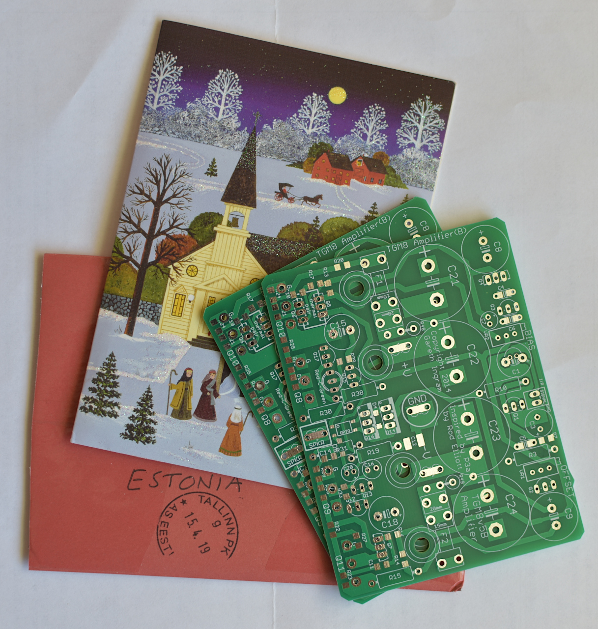
So very cute!! I've never seen a Christmas card this wee little size! Next Christmas--well just a bit before then, I'm gonna get some.
The boards are good!
Your amplifier is considerably more powerful than I need but it has capacity to coddle commonplace headphone sources that I'd like to use (at least 4x better at input, before gain is applied). Awesome!
So, the ask is a schematic aimed at 35+35vdc rail voltage. Well, I happen to have a lot of on-hand materials for that size, ready to go.
Last edited:
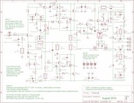
C3 orientation if not bipolar
Hi Gareth,
Just wanted to point out that C3 polarity may be wrong on the schematic and PCBs. You specify a bipolar on this schematic which avoids the issue, but just in case someone decides to use a polarized one...
PS: Have you made up those speaker cables yet?
Hi Gareth,
Just wanted to point out that C3 polarity may be wrong on the schematic and PCBs. You specify a bipolar on this schematic which avoids the issue, but just in case someone decides to use a polarized one...
PS: Have you made up those speaker cables yet?
Attachments
Question: Can I use 40V FETs in the protection circuit if using +/-39V rails?
I can't see any reason why not since the FETs only have to block the rail voltage, worst case. I cannot see any reason why the protection circuit would need to block 2X the rail voltage.
Or is my reasoning flawed?
I can't see any reason why not since the FETs only have to block the rail voltage, worst case. I cannot see any reason why the protection circuit would need to block 2X the rail voltage.
Or is my reasoning flawed?
Member
Joined 2009
Paid Member
Hi Gareth,
Just wanted to point out that C3 polarity may be wrong on the schematic and PCBs. You specify a bipolar on this schematic which avoids the issue, but just in case someone decides to use a polarized one...
PS: Have you made up those speaker cables yet?
You are correct, I did build the amp with C3 the wrong way around. See post 645 (also referenced in the first post). The voltage being so low it caused no harm and no audible issues either. I did, later, reverse the polarity on my build to make it correct.
Member
Joined 2009
Paid Member
Question: Can I use 40V FETs in the protection circuit if using +/-39V rails?
I can't see any reason why not since the FETs only have to block the rail voltage, worst case. I cannot see any reason why the protection circuit would need to block 2X the rail voltage.
Or is my reasoning flawed?
The reasoning is fine if we had no load, or a simple resistive load. Although you always want some safety factor, i.e. if the max voltage on the board was 39V you'd want to allow more than 1V safety margin to the max rating of your components. Two reasons why this isn't safe:
a) your rail voltage will rise above nominal under no-load or low-load conditions due to the regulation of your power transformer and there will be variations in the mains voltage at the wall socket.
b) the speaker is a reactive load, it has capacitance and inductance and can generate back e.m.f. If you suddenly cut the current supply to the speaker (solid state relay 'opens') you can generate voltages well in excess of the rail voltage. Therefore, you want to have your FETs rated at much higher voltages. It's relatively easy to find 150V rated FETs. The FETs can be damaged by the back emf so I have 'catch diodes' across the output-rails which helps to shunt reverse bias back-emf spikes to the power supply.
Most important is to have maximum SOAR for the FETs so that they can endure the stress of carrying current and voltage during a turn-off event for the brief time that it takes the circuit to recognize a fault condition and act on it. In this regards, the circuit could be made more robust with a speed-up capacitor but I haven't explore this.
I haven't forgotten your request - I'll take a look - have been a bit busy.So, the ask is a schematic aimed at 35+35vdc rail voltage. Well, I happen to have a lot of on-hand materials for that size, ready to go.
Thanks for the reply Gareth.
That was pretty much my thinking except...
I think I might take a (very small) risk on the IRF1404Zs in my parts box because:
* FETs have an SOA defined by power dissipation. I cannot see how in this application the can dissipate much power because they only switch occasionally
* semi manufacturers have a guard band on their ratings (lower on newer devices in general) and the IRF1404Z is fully avalanche rated
* since you included catch diodes the worst case is an inductive "clamped" load
* my mains is high (about 245V) most of the time - this gives the 39V rails. Seems unlikey that the amp should fail on the odd occasion the voltage is higher than this. The rail voltage will tend to sag at high load currents, which will help with the SOA/switching time concern.
I suppose I could measure the avalanche voltage for the actual parts.
I was just thinking about how close to the rails the output can swing (with a resistive load).
It's actually very hard to figure out because the base current of Q10 gets added to the collector current of Q6 and provides gate drive for Q8 due to the voltage drop across R21 (+ the Vbe of Q10). Lots depends on the FET threshold voltage and its transconductance.
It looks like the output could get to within ~3 to ~6V of the rail voltage. Is that a reasonable estimate?
Member
Joined 2009
Paid Member
Hi
Any recommendations for a pair of tweezers for general SMT work? For 0805 LCR and up. Something Mouser offers, hobby use but I value good tools.
thanks
I don't remember which model and where I got it from but use some plastic tweezers with flat ends that are heat resistance and ESD safe. They cost me a few dollars from digikey: 243-1379-ND and they work just fine. I had not worked much with SMT before my TGM7 and I like it.
I expect you can find similar from Mouser.
Attachments


- Home
- Amplifiers
- Solid State
- TGM8 - my best amplifier, incredible bass, clear highs, no fatigue (inspired by Rod Elliot P3a)