Salas DCG3!
A set of full range speakers too.
Fane 12-250TC.
Mine SX still under construction....
Very nice Thimios!
")
Where i can find pcb for that salas DCG3 pre amp?
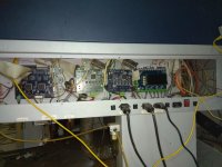
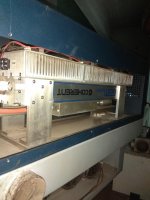
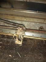
Thanks bonsai, i had to repair my friend's laser machine for this lettering procedure.Very nice Thimios!
Difficult work, many hours, many days, a lot of troubles.....
Attachments
Last edited:
Hi, I'm returning to my NX-AMP build after several years away from it. Hoping to get a little help here.
Previously, I was in the final start-up stage, but had some issues getting it stabilized. Last Communication I had with Bonsai, it was suggested that I purchase new output transistors because I had got them from ebay and they could be Counterfeit.
1) Can you suggest a reliable source for the matched output Transistors?
2) Is there anything else that I should be aware of, changes etc?
Late 2017 is when I stopped the work..
Back on the Ovation NX. Installed new output transistors. I tried to adjust current across +ve and I'm getting slow drift while adjusting R6 and cant get it to stabilize. It's not as bad as I had before but looks like the same issue, about 5 minutes to drift 30ma. R20 is 220 ohms and I believe I changed it from 33 ohms previously. The installed Q20 is BC560C and I believe it is equivalent to BC557C.
I'll continue to search for the issues. Any suggestion will be appreciated
I'll continue to search for the issues. Any suggestion will be appreciated
Joe,
The bias current will take about 10 minutes to settle.
1. Adjust it to minimum
2. Drive the amp at circa 1/3 power for 20 minutes
3. Adjust the bias current to the specified value
This completes bias set-up
The amp will usually power up at about 1/2 to 2/3 of the value set above and then take a few minutes to reach the set value. It will drift around by 5-10% over a 1-2 minute window under normal operating conditions - depends on power level, ambient temperature and thermal conditions (eg exposure to air currents etc) in tne amolifier housing.
My NX Build
I have populated the PS+Protection and both amplifier boards.
The PS+Protection board passes the test Andrew outlined in his instructions. I am using the transformer Andrew recommended from Tiger Toroids. This is giving me +/- 52V rails.
Amplifier Testing and Setup (page 41)
Step 9: On each of the amplifier boards I have adjusted Iq for 300mA after board has stabilized for 20 minutes. Note: After 20 minutes my heatsink temperature was around 35c.
Step 12: The outputs emitters should read 42mV +/-5mV. I am OK here. They seem a little low at 38mV on Q2/Q4 and 40mV on Q1/Q5. But they are with the 5mV tolerance.
Step 16 (offset): I can adjust the offset to 0V. However, the readings slowing drift up and down. Sometimes up to +10mV or down to -10mV. Back and forth. These readings seem very sensitive to temperature. I can blow on the amp card and see a increase in the speed of the drifting offset voltage.
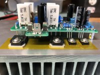
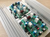
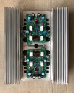
After the boards were completed I noticed that Andrew soldered his boards touching or sitting directly on top of the heatsink devices. I left room between the amp boards and the heatsink devices. Was there some thermal considers for Andrews approach?
Here is a picture of my board/heastsink. Am I OK here? Or should I move the board to sit on top of the heatsink devices?
I have populated the PS+Protection and both amplifier boards.
The PS+Protection board passes the test Andrew outlined in his instructions. I am using the transformer Andrew recommended from Tiger Toroids. This is giving me +/- 52V rails.
Amplifier Testing and Setup (page 41)
Step 9: On each of the amplifier boards I have adjusted Iq for 300mA after board has stabilized for 20 minutes. Note: After 20 minutes my heatsink temperature was around 35c.
Step 12: The outputs emitters should read 42mV +/-5mV. I am OK here. They seem a little low at 38mV on Q2/Q4 and 40mV on Q1/Q5. But they are with the 5mV tolerance.
Step 16 (offset): I can adjust the offset to 0V. However, the readings slowing drift up and down. Sometimes up to +10mV or down to -10mV. Back and forth. These readings seem very sensitive to temperature. I can blow on the amp card and see a increase in the speed of the drifting offset voltage.
- Is this normal?
- Can I assume that once the amplifiers are housed in an enclosure that the offset will be more stable?
After the boards were completed I noticed that Andrew soldered his boards touching or sitting directly on top of the heatsink devices. I left room between the amp boards and the heatsink devices. Was there some thermal considers for Andrews approach?
Here is a picture of my board/heastsink. Am I OK here? Or should I move the board to sit on top of the heatsink devices?
Attachments
Last edited:
Dennis,
Your attachment to the heat sink looks ok!
The drift you see is due to thermal gradients across the input devices. It may be a bit lower if you had just seated the PCB directly onto the output devices as I did, but it’s a non issue.
Once your amp is boxed up and loosed to settle thermally, the drift window will decrease.
Make sure your source output is AC coupled.
Your bias current is set correctly, you are good to go! Remember the output emitter degenerate resistors are 5% tolerance and you then also have the Vbe spread in the output devices so there will be some variation in the emitter resistor voltage drops.
Last edited:
My NX Build
Before committing this project to a proper enclosure I temporarily laid out my amp on plywood for listening test. This also gives me some practice on wiring as recommended in Andrew's "Ground Loops" pdf on his website hifisonix.com.
It sounds great. I am not good with fancy descriptions.
One question on the Power Supply and Speaker Mute Board. There is a good 3 or 4 second delay before the SSLR engages. However, turn-off time is not instantaneous. I estimate about a half a second before the indicator LED goes out and the music is muted.
It is my understanding that the mute turn-off time should be in the region of 50 micro-seconds.
Attachments
Hello Dennis,
Perhaps my description of the muting function should have been clearer. There is a slight delay before the speakers are disconnected by the solid state relay during a normal power down cycle. The 50us really refers to the mosfet Relay + drive circuit switching time. Ideally you want to keep this below c. 100 us in order to remain within the energy rating of the mosfet.
When the amplifier powers down normally, the rails will collapse and 50 or 100 milli seconds later the speakers will disengage.
If the amplifier develops a fault eg short circuit across the speaker or a large DC offset, the protection circuit will switch very quickly - within 10s of microseconds.
The important thing is, you should not get any loud thumps when you power down normally.
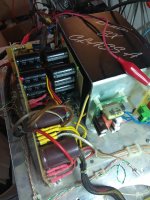
Great that you are still supporting builders Andrew / Bonsai! Quite a while ago that I have been here. Unfortunately I have not had much time to spare. A few weeks ago I came across the boards again. Some progress, pasito a pasito as our Latam friends say .
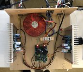
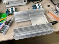
The idea is to make a relatively compact build in terms of height. It was not easy to find a proper heatsink for that, so I fabricated something instead. Those radiators were actually spares for the KSA-100 clone Normally air is forced through them for optimal convection, but I expect this will be sufficient. A bonus is that it provides a nice shield for the cables, as I could route them underneath. The whole unit weighs more or less 3.5 kg.
.The idea is to make a relatively compact build in terms of height. It was not easy to find a proper heatsink for that, so I fabricated something instead. Those radiators were actually spares for the KSA-100 clone
Normally air is forced through them for optimal convection, but I expect this will be sufficient. A bonus is that it provides a nice shield for the cables, as I could route them underneath. The whole unit weighs more or less 3.5 kg.Attachments
Last edited:
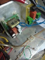
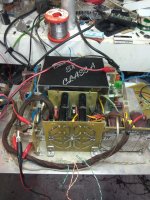
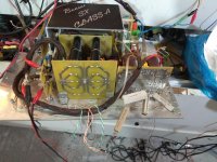
Service to SX amplifier
Last two days i have problem with periodically burning fuses in the primary side of transformer in my SX amplifier.
I have used 2A slow blow and a soft start with 5x10ohm/5w.
My caps bank is 67.000uf/ rail.
I haven't any problem up to now.
I'm sure that problem is at the power supply because keep blowing fuses periodically without any load.
Not sure what happen i manage to increase the soft start resistors to 5x 22ohm(88ohm).
Measured primary side current is 400mA at the moment of power on when no load in the secondary side,just caps bank.
A. C Voltage drop on soft start resistors is 20v RMS, time before full start is about 2 sec.
Fuses are new old stock Philips.
Your opinion please.
Is it necessary to increase the soft start resistors or time further?
Given the fact that transformer is about 800 VA and the caps bank is 67000uf /rail is the 2A Fuse suitable?
Attachments
Last edited:
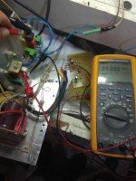
Hi Bonsai, thanks for answer!
Main voltage is about 225v.
Current at transformer primary side, when secondary is open circuit, is about 200mA.
Fuse body marked as T2A/250v.
Is from the same box that i used up to now in this position.
Another transformer measured for comparision, same things, current at the primary coil, when secondary is open circuit, is about 200mA.
Both transformer are salvaged from UPS.
Same dimensions, different manufacturers.
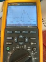
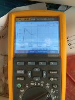
PS. Start current (caps bank+16R load) is most times 0,8-1A.See below.
Picture in post #2436, 2 A captured when playing with the power switch quickly. On-off-on-off, on.
Main voltage is about 225v.
Current at transformer primary side, when secondary is open circuit, is about 200mA.
Fuse body marked as T2A/250v.
Is from the same box that i used up to now in this position.
Another transformer measured for comparision, same things, current at the primary coil, when secondary is open circuit, is about 200mA.
Both transformer are salvaged from UPS.
Same dimensions, different manufacturers.
PS. Start current (caps bank+16R load) is most times 0,8-1A.See below.
Picture in post #2436, 2 A captured when playing with the power switch quickly. On-off-on-off, on.
Attachments
Last edited:
That’s a very high primary current with the secondary’s open circuit Thimios.
Does the fuse only blow if you have the secondary’s connected to the power supply?
Note that the inrush current of the transformer itself (not related to cap charge) can be many tens of amps if you catch it at the wrong time on the mains cycle at switch on.
In an ideal transformer with open secondary’s after the switch on inrush current of the transformer, the current draw Should be 10-20 mA.
- Home
- Amplifiers
- Solid State
- SX-Amp and NX-Amp