...like this - see picture...
...between > 2MHz and 500kHz...
the IXYS could be destroyed...
Yes, those were the problems I saw with the totem pole tied to the variable rail.
Obviously the totem pole drive will vary as the rail moves around.
The gate can be protected with a zener and the totem pole driven from a zener to stabilise the frequency (probably both needed) but it's not efficient, kind of clumsy.
And I want to avoid separate sub rails so that the Class H module can be a simple drop in replacement for a class B+.
But separate floated sub rails would be acceptable if I/we/someone can't find a better solution.
My intuition is that there must be hi-side driver ICs for exactly this problem.
Some of them have built in boot strap diodes.
Not sure how that would work when each side becomes inactive as the output moves to the other polarity.
I think there are some ICs that even have their own built-in oscillator and capacitor pump so there is no minimum frequency, seems like it would work here.
I will continue to search but suspect that someone familiar with SMPS circuitry could take one look and know exactly the correct IC to do this neatly.
I will try to contact Chocoholic...
Thanks, maybe he is the one who knows.😉
Best wishes
David
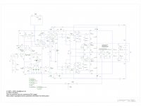
PRELIMINARY NEW CLASS G (c) astx and DaveZan
DaveZan has allowed me to publish this model of a high performance Class G implementation. The idea is from Dave and I have contributed a modified version of the gate voltage boot strap for the IXYS power mosfets. Currently the schematic has been only simulated using ngspice but will find it's way to a breadboard perhaps the next weeks...
Attached the schematic and some simulation data...
Have fun, Toni
DaveZan has allowed me to publish this model of a high performance Class G implementation. The idea is from Dave and I have contributed a modified version of the gate voltage boot strap for the IXYS power mosfets. Currently the schematic has been only simulated using ngspice but will find it's way to a breadboard perhaps the next weeks...
Attached the schematic and some simulation data...
fourier op1.freq tran1.output
Fourier analysis for output:
No. Harmonics: 10, THD: 0.000328905 %, Gridsize: 500, Interpolation Degree: 1
Harmonic Frequency Magnitude Phase Norm. Mag Norm. Phase
-------- --------- --------- ----- --------- -----------
0 0 -0.000464 0 0 0
1 2e+04 4.18 -2.56 1 0
2 4e+04 2.282e-06 32.49 5.459e-07 35.06
3 6e+04 9.457e-06 176.4 2.262e-06 179
4 8e+04 7.102e-06 146.5 1.699e-06 149.1
5 1e+05 3.677e-06 130 8.797e-07 132.5
6 1.2e+05 2.972e-06 131.9 7.109e-07 134.5
7 1.4e+05 1.079e-06 9.718 2.58e-07 12.28
8 1.6e+05 3.183e-06 63.82 7.615e-07 66.38
9 1.8e+05 3.214e-06 -118 7.689e-07 -115
LRail power : 11.2776 W
HRail power : 11.1823 W
Total power : 22.46 W
Output power : 1.09217 W
Power dissipation: 21.3678 W
fourier op1.freq tran5.output
Fourier analysis for output:
No. Harmonics: 10, THD: 0.0022713 %, Gridsize: 500, Interpolation Degree: 1
Harmonic Frequency Magnitude Phase Norm. Mag Norm. Phase
-------- --------- --------- ----- --------- -----------
0 0 -0.0146 0 0 0
1 2e+04 59.3 -2.56 1 0
2 4e+04 0.0009999 158.9 1.686e-05 161.5
3 6e+04 0.0005738 53.56 9.677e-06 56.12
4 8e+04 3.875e-05 25 6.534e-07 27.56
5 1e+05 0.000423 -6.91 7.133e-06 -4.35
6 1.2e+05 0.000106 139.8 1.788e-06 142.4
7 1.4e+05 0.0003798 -37.2 6.405e-06 -34.6
8 1.6e+05 8.341e-05 115.2 1.407e-06 117.7
9 1.8e+05 0.0003768 -82.8 6.354e-06 -80.2
LRail power : 4.57875 W
HRail power : 344.912 W
Total power : 349.491 W
Output power : 219.74 W
Power dissipation: 129.751 W
fourier op1.freq tran7.output
Fourier analysis for output:
No. Harmonics: 10, THD: 0.00203959 %, Gridsize: 500, Interpolation Degree: 1
Harmonic Frequency Magnitude Phase Norm. Mag Norm. Phase
-------- --------- --------- ----- --------- -----------
0 0 -0.015 0 0 0
1 2e+04 62.26 -2.56 1 0
2 4e+04 0.00112 177.8 1.798e-05 180.4
3 6e+04 0.000441 67.41 7.083e-06 69.97
4 8e+04 9.265e-05 -85.4 1.488e-06 -82.8
5 1e+05 0.0002285 -14.3 3.67e-06 -11.8
6 1.2e+05 0.0001619 162.3 2.6e-06 164.8
7 1.4e+05 0.0001797 -23.8 2.886e-06 -21.2
8 1.6e+05 0.0001214 120.7 1.949e-06 123.3
9 1.8e+05 0.0001753 -78.2 2.815e-06 -75.6
LRail power : 4.48095 W
HRail power : 362.695 W
Total power : 367.176 W
Output power : 242.263 W
Power dissipation: 124.913 W
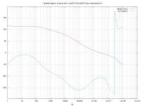
#---------------------------------------------------------------------
# loopgain results for plot ac3
#---------------------------------------------------------------------
GM : -22.0747
PM : -106.091
3db : 2.55753E+07
0db : 2.71573E+06
dc gain : 116.632
6db : 6.0734E+06
Rload1 during simulation was 8 Ohm. VAS Diode in situ.Fourier analysis for output:
No. Harmonics: 10, THD: 0.000328905 %, Gridsize: 500, Interpolation Degree: 1
Harmonic Frequency Magnitude Phase Norm. Mag Norm. Phase
-------- --------- --------- ----- --------- -----------
0 0 -0.000464 0 0 0
1 2e+04 4.18 -2.56 1 0
2 4e+04 2.282e-06 32.49 5.459e-07 35.06
3 6e+04 9.457e-06 176.4 2.262e-06 179
4 8e+04 7.102e-06 146.5 1.699e-06 149.1
5 1e+05 3.677e-06 130 8.797e-07 132.5
6 1.2e+05 2.972e-06 131.9 7.109e-07 134.5
7 1.4e+05 1.079e-06 9.718 2.58e-07 12.28
8 1.6e+05 3.183e-06 63.82 7.615e-07 66.38
9 1.8e+05 3.214e-06 -118 7.689e-07 -115
LRail power : 11.2776 W
HRail power : 11.1823 W
Total power : 22.46 W
Output power : 1.09217 W
Power dissipation: 21.3678 W
fourier op1.freq tran5.output
Fourier analysis for output:
No. Harmonics: 10, THD: 0.0022713 %, Gridsize: 500, Interpolation Degree: 1
Harmonic Frequency Magnitude Phase Norm. Mag Norm. Phase
-------- --------- --------- ----- --------- -----------
0 0 -0.0146 0 0 0
1 2e+04 59.3 -2.56 1 0
2 4e+04 0.0009999 158.9 1.686e-05 161.5
3 6e+04 0.0005738 53.56 9.677e-06 56.12
4 8e+04 3.875e-05 25 6.534e-07 27.56
5 1e+05 0.000423 -6.91 7.133e-06 -4.35
6 1.2e+05 0.000106 139.8 1.788e-06 142.4
7 1.4e+05 0.0003798 -37.2 6.405e-06 -34.6
8 1.6e+05 8.341e-05 115.2 1.407e-06 117.7
9 1.8e+05 0.0003768 -82.8 6.354e-06 -80.2
LRail power : 4.57875 W
HRail power : 344.912 W
Total power : 349.491 W
Output power : 219.74 W
Power dissipation: 129.751 W
fourier op1.freq tran7.output
Fourier analysis for output:
No. Harmonics: 10, THD: 0.00203959 %, Gridsize: 500, Interpolation Degree: 1
Harmonic Frequency Magnitude Phase Norm. Mag Norm. Phase
-------- --------- --------- ----- --------- -----------
0 0 -0.015 0 0 0
1 2e+04 62.26 -2.56 1 0
2 4e+04 0.00112 177.8 1.798e-05 180.4
3 6e+04 0.000441 67.41 7.083e-06 69.97
4 8e+04 9.265e-05 -85.4 1.488e-06 -82.8
5 1e+05 0.0002285 -14.3 3.67e-06 -11.8
6 1.2e+05 0.0001619 162.3 2.6e-06 164.8
7 1.4e+05 0.0001797 -23.8 2.886e-06 -21.2
8 1.6e+05 0.0001214 120.7 1.949e-06 123.3
9 1.8e+05 0.0001753 -78.2 2.815e-06 -75.6
LRail power : 4.48095 W
HRail power : 362.695 W
Total power : 367.176 W
Output power : 242.263 W
Power dissipation: 124.913 W
#---------------------------------------------------------------------
# loopgain results for plot ac3
#---------------------------------------------------------------------
GM : -22.0747
PM : -106.091
3db : 2.55753E+07
0db : 2.71573E+06
dc gain : 116.632
6db : 6.0734E+06
Have fun, Toni
Attachments
-
 sa2019-ixys-minimized_schematic.jpg497.5 KB · Views: 1,306
 -
 tian_combined1.png17.8 KB · Views: 1,355
 -
 soa_combined7.png15.9 KB · Views: 225
 -
 soa_combined4.png16 KB · Views: 203
 -
 soa_combined3.png16.4 KB · Views: 210
 -
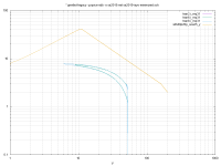 soa_combined2.png14.8 KB · Views: 220
 -
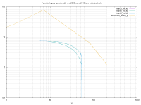 soa_combined1.png15.1 KB · Views: 247
 -
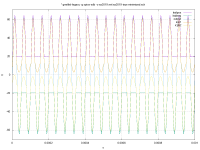 output_lvl_2.1v_3.png20.7 KB · Views: 990
 -
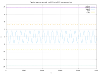 output_lvl_0.141v_1.png13.1 KB · Views: 1,004
 -
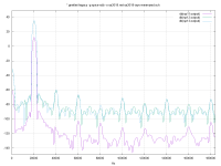 fftplot_combined.png22.8 KB · Views: 1,346
Last edited:
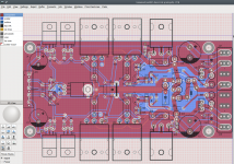
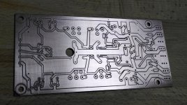
The 2nd Covid19 lockdown 😱 gave me some sparetime to design the prototype PCB for the SA2021 New Class H output stage prototype.
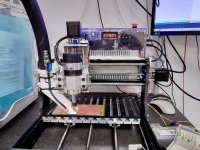
Currently I'm machining the prototype pcb using a diy cnc
(cnc3018 based; heavy redesigned: own designed Z-axis, 3 phase controlled spindle 12k rpm, better stepper motors, case for the electronics).
Have fun!
Happy new year!
Toni
Currently I'm machining the prototype pcb using a diy cnc
(cnc3018 based; heavy redesigned: own designed Z-axis, 3 phase controlled spindle 12k rpm, better stepper motors, case for the electronics).
Have fun!
Happy new year!
Toni
Attachments
Last edited:
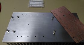
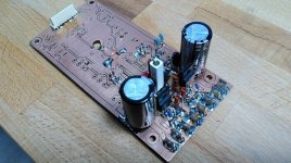
Read to be soldered next year! 😉
Doublesided pcb of course...
BR, Toni
Doublesided pcb of course...
BR, Toni
Attachments
Last edited:
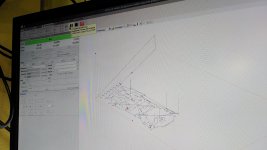
I like the vacuum cleaner.
One of my DIY 3d designs using QCAD/openscad and afterwards 3D printed.
BR, Toni
I have successfully milled 0.254 mm clearing between tracks. The clearing between tracks for the prototype is about 0.35 mm. I depends on the graver you use. I'm using a 15 degree, 0.1mm wide graver to mill the tracks.
Last edited:
This engraver/router method certainly has its limitations with respect to a double sided pcb that requires plated holes. The layout has to be done with that process in mind. As an example, having a layer change connection under one of those big ecaps is a no-no. These days the cost, time savings is marginal and the quality is just not worth it imo. Sorry Tony but it does not make any economical sense anymore esp adding in the cost of the machine.
You are right and not! Don't want to wait 14 days until prototype arrives. And even if the pcb is without pth it showed me at least 2 mistakes I made during design.
The mini cnc is worth every cent - also the prototype heatsink milling saved me a lot of time.
😉
The mini cnc is worth every cent - also the prototype heatsink milling saved me a lot of time.
😉
- Home
- Amplifiers
- Solid State
- 2stageEF high performance class AB power amp / 200W8R / 400W4R