I thought the amp powered up but with a DC offset and thus the speaker relay (DC offset protection) cutting in? Is that not correct ")
Lets start again from the beginning. The first check is always to confirm the main DC rails are present. That means checking the minus and plus 55 volts (it looks like on the diagram) that supply the front end stages and also that the supplies to the output stage are correct.
I can mark those points on the diagram.
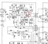
Engineer mode The 39k's are high wattage parts stood off the PCB because they get very hot. If one is cool then it points to a problem in that area, either the resistor itself or the components it feeds. Its a quick check that needs no test equipment apart from a finger.
I would need the amp in front of me to advise on how to access it all but I would imagine it all comes apart fairly easily.
Lets start again from the beginning. The first check is always to confirm the main DC rails are present. That means checking the minus and plus 55 volts (it looks like on the diagram) that supply the front end stages and also that the supplies to the output stage are correct.
I can mark those points on the diagram.
Engineer mode
The 39k's are high wattage parts stood off the PCB because they get very hot. If one is cool then it points to a problem in that area, either the resistor itself or the components it feeds. Its a quick check that needs no test equipment apart from a finger.I would need the amp in front of me to advise on how to access it all but I would imagine it all comes apart fairly easily.
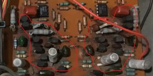
Look at this resistor. One end goes to the positive supply at the top, the other end goes via a transistor base/emitter junction and low value resistor to the negative supply at the bottom.
So without knowing the component id on the board we can still check the supplies by seeing what the voltages are on those resistors. At least one of the pair per channel should have something like +55 and -55 volts (very approximately) as measured from chassis to each leg.
So without knowing the component id on the board we can still check the supplies by seeing what the voltages are on those resistors. At least one of the pair per channel should have something like +55 and -55 volts (very approximately) as measured from chassis to each leg.
Attachments
(Sorry...) FORGOT TO ATTACH THESE PHOTOS...
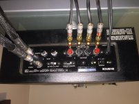
Relating to questions around removing the board or not?
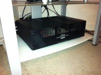
(It's an old wooden chassis, so not like modern, modular amps...)
Relating to questions around removing the board or not?
(It's an old wooden chassis, so not like modern, modular amps...)
Attachments
Last edited:
Look at this resistor. One end goes to the positive supply at the top, the other end goes via a transistor base/emitter junction and low value resistor to the negative supply at the bottom.
So without knowing the component id on the board we can still check the supplies by seeing what the voltages are on those resistors. At least one of the pair per channel should have something like +55 and -55 volts (very approximately) as measured from chassis to each leg.
Mooly,
Are you saying that by measuring "across" all of the Resistors while in circuit - with the amp powered down - I have wasted my time?
Are you saying that I should have measured the resistance of each Resistor with one meter pin on one (or other) of the Resistor legs - and the other meter pin on the ground? (And if so, this needed to be done while the amp is powered up?)
As below, the amp does not power up as the Protection Circuit kicks-in and halts precedings. It does not warm up. Nothing. The Protection Circuit (Red) LED just winks on and off, instead of turning Green and powering up.
Sadly, this precludes any powered-up testing or measuring.
Last edited:
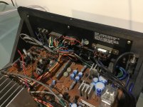
Hard to say. The boards look like they would come free up to a point (undo the nuts visible). Does that rear panel come loose? That could be a way to get more access.
The boards have that look of running hot about them (discoloured PCB) and that suggests there will be poor soldered joints around hot running components. Typically the joint cracks over time.
Ideally you should gather as much information as possible by careful voltage checks before doing anything though.
Mooly,
Are you saying that by measuring "across" all of the Resistors while in circuit - with the amp powered down - I have wasted my time?
Are you saying that I should have measured the resistance of each Resistor with one meter pin on one (or other) of the Resistor legs - and the other meter pin on the ground? (And if so, this needed to be done while the amp is powered up?)
As below, the amp does not power up as the Protection Circuit kicks-in and halts precedings. It does not warm up. Nothing. The Protection Circuit (Red) LED just winks on and off, instead of turning Green and powering up.
Measuring resistance in circuit often gives misleading results because of interaction with other components that appear in parallel with the part you are trying to measure. Even reversing the meter leads can give two totally different results because the polarity of the meters test voltage bias the semiconductors in different ways depending on polarity.
We always measure across the component for resistance, not from chassis to the part and never with any power supplied to the circuit. Residual voltage in any capacitors, even if only a few tens of millivolts can also affect readings.
As I mentioned before, the exceptions are reading low value resistors where often you can get a fairly reliable result in circuit.
If the protection circuit kicks in then the amp is powering up (my definition of powering up). Not powering up means totally dead
Checking power supplies is the first thing to do in any fault finding exercise. We have to know if the supplies to the amplifier are correct before we can go on to determine if the voltage measurements we take within the amplifier circuitry are valid.
Age of Amp: Circa 1981!!!
PITBUL
Sorry I missed your question below.
This amp is from around 1981. It looks like it has never been re-capped, but none of the caps look damaged or cooked...
MOOLY
Maybe you are right about the hot running, but this amp has never run very hot for me.
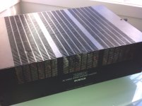
I believe the discoloured boards are not from (over)hot running, but from the fact that this amp sat in someone's (dry) garage for decades - and the open-vent style cover (see pic) allowed years of grunge to accumulate on the circuit boards.
I've been busy cleaning it off.
Stinks a bit, particularly when it is powered up!
(Before this problem emerged...)
PITBUL
Sorry I missed your question below.
This amp is from around 1981. It looks like it has never been re-capped, but none of the caps look damaged or cooked...
MOOLY
Maybe you are right about the hot running, but this amp has never run very hot for me.
I believe the discoloured boards are not from (over)hot running, but from the fact that this amp sat in someone's (dry) garage for decades - and the open-vent style cover (see pic) allowed years of grunge to accumulate on the circuit boards.
I've been busy cleaning it off.
Stinks a bit, particularly when it is powered up!
(Before this problem emerged...)
Attachments
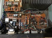
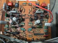
If you look at the boards you can see how the colour changes around the parts of the circuit that run hottest. That's normal on this type of PCB material (phenolic resin type) and is due to chemical changes.
You can actually wash PCB's (although I'm not suggesting you do that here) and bring them up like new... although the discolouration would remain.
Post#10:
Washing an amplifier board
You can actually wash PCB's (although I'm not suggesting you do that here) and bring them up like new... although the discolouration would remain.
Post#10:
Washing an amplifier board
Attachments
Board Discolouration
MOOLY
Those discoloured areas are just where I cannot reach with my toothbrush lol!
All the boards looked like that originally...
The boards are actually a nice circuit board green glass underneath!
If you look at the boards you can see how the colour changes around the parts of the circuit that run hottest. That's normal on this type of PCB material (phenolic resin type) and is due to chemical changes.
You can actually wash PCB's (although I'm not suggesting you do that here) and bring them up like new... although the discolouration would remain.
Post#10:
Washing an amplifier board
MOOLY
Those discoloured areas are just where I cannot reach with my toothbrush lol!
All the boards looked like that originally...
The boards are actually a nice circuit board green glass underneath!
OK this is where you have the advantage over me in having the real thing rather than working from pictures.
If that discolouration is grime then it might be worth setting your meter on a high ohms range (the range that can measure very high value meg ohms) and seeing if that dirt is conductive. Just prod the dirt with the probes as close together as possible and see if you get a reading.
Alternatively, when the amp is on and if there is supply voltage present then see if you can get a voltage reading from chassis to the dirt on the board. If either test comes back with a positive result then the dirt is conductive and that could upset the circuit operation.
this is where you have the advantage over me in having the real thing rather than working from pictures.If that discolouration is grime then it might be worth setting your meter on a high ohms range (the range that can measure very high value meg ohms) and seeing if that dirt is conductive. Just prod the dirt with the probes as close together as possible and see if you get a reading.
Alternatively, when the amp is on and if there is supply voltage present then see if you can get a voltage reading from chassis to the dirt on the board. If either test comes back with a positive result then the dirt is conductive and that could upset the circuit operation.
@SONDEKNZ
My recomendation is that you change all electrolytic capacitors on control board. Their lifetime is gone (it is suspected that not only working hours degrade quality of the capacitor, but also time when you don't use the equipment, it is more critical when you switch on your equipment after 1 year or more, capacitor may be your main problem).
Mooly helped you a lot, but we don't see any resault, I sugest that you try change the component already mentioned in my posts, it is lot quicker for you.
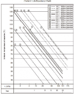
I attached the lifetime diagram from one reputable producer of capacitors (ELNA) to show you importance of the ELCO parts.
We supose that ambient temperature inside equipment is about 45-50C.
From diagram you can read what is expected lifetime of the capacitor (nr 1 is proposed, as I can assume 85C is max capacitor temperature for that time of production is often).
Tere are few more factors which are important too, but for so old amplifier it is now irrelevant.
Good luck
My recomendation is that you change all electrolytic capacitors on control board. Their lifetime is gone (it is suspected that not only working hours degrade quality of the capacitor, but also time when you don't use the equipment, it is more critical when you switch on your equipment after 1 year or more, capacitor may be your main problem).
Mooly helped you a lot, but we don't see any resault, I sugest that you try change the component already mentioned in my posts, it is lot quicker for you.
I attached the lifetime diagram from one reputable producer of capacitors (ELNA) to show you importance of the ELCO parts.
We supose that ambient temperature inside equipment is about 45-50C.
From diagram you can read what is expected lifetime of the capacitor (nr 1 is proposed, as I can assume 85C is max capacitor temperature for that time of production is often).
Tere are few more factors which are important too, but for so old amplifier it is now irrelevant.
Good luck
Attachments
ELECTROLYTIC RE-CAPPING!
PITBUL
Thanks for this. Yes. I can see that this is inevitable.
And if I am taking the boards out for such an exercise, it would seem stupid to not replace all of the major Resistors - particularly those METAL OXIDE jobbies that Mooly mentioned tend to fail.
I would also up the wattage values on many items - particularly in the POWER SUPPLY area of the circuit.
(Not sure why amp designers seem to want to get by with the lowest wattage safety margin imaginable. The cost of higher wattage components is negligible. So I will probably double-down - and more in the Power Supply!)
All this turns a quick fix into a major project. No way around it I guess.
I note that you suggest changing just the electrolytic capacitors. Is it your opinion that the other types of caps in these amps just march on and on and are worth leaving alone?
CONDUCTIVE CIRCUIT BOARD GRUNGE???
MOOLY
I have attached another photo, because I don't think the boards are quite as grimey as they appear in your last pic.
As you say, there's nothing like having the amp in your hands, before your very eyes!
I have tried what you have suggested. No reading. So, the grime has not got so bad that it is creating shorts.
I suspected this would be the case as I have had this amp successfully running previously - for months and months - in its current state.
Nevertheless, there is no way I would leave the boards uncleaned, if I was to take them out and tackle the caps and resistors project mentioned to PITBUL below.
I've read some pretty good threads on circuit board cleaning. I'm a believer!
Attachments
GEARING UP!
All of these projects are really hard without the right gear.
Personally, I have always found solder-sucking hard work - and I ruined a circuit trace on one occasion. (Had to order a whole new board...)
Facing the prospect of swapping out dozens of old caps and resistors... I finally decided to bite the bullet!
I've ordered a proper solder station which includes a solder-sucker pump!
(I hope some of you can vouch for this little machine...)
Attachments

REPLACE 4558D OPAMP FIRST!
PITBUL
These items appear to be about 50-cents each, so does it make sense to replace both 4558D OPAMPS that appear on the same board?
Secondly, if I replaced the 4558D OPAMP in the (problematic) RIGHT CHANNEL only, wouldn't the suspect old capacitors damage the new OPAMP again?
In summary, whilst I would like to be able to replace one part and figure out who the culprit was, I don't think it will be efficient to replace just one part at a time. At least that's my thinking.
(I welcome your expertise here...)
First I suggested to replace 4558, I suspected that it is damaged because of bad filtration caused by old capacitors.
Other types of caps should be ok.
PITBUL
These items appear to be about 50-cents each, so does it make sense to replace both 4558D OPAMPS that appear on the same board?
Secondly, if I replaced the 4558D OPAMP in the (problematic) RIGHT CHANNEL only, wouldn't the suspect old capacitors damage the new OPAMP again?
In summary, whilst I would like to be able to replace one part and figure out who the culprit was, I don't think it will be efficient to replace just one part at a time. At least that's my thinking.
(I welcome your expertise here...)
If I shall do repairing I'll replace only 4558 in bad channel, check if it is working, after that I'll buy capacitor from reputable source and manufacturer and replace those on the power supply section/control board. I'll leave big capacitors for amp section.
In the future if there are some dissapoitment in the sound, or measured values on the supply amp rails, I'll change the big caps. That's my philosophy, so adopt yours in this case.
In the future if there are some dissapoitment in the sound, or measured values on the supply amp rails, I'll change the big caps. That's my philosophy, so adopt yours in this case.
That looks a nice bit of kit When it comes to desoldering its very much a case of what you get used to and what you are comfortable with. I like solder braid tbh and find it very quick and easy to work with.
The 4558 opamp… I would be very surprised if there were an issue there but a simple check would just be to deliberately short pin 7 to ground. The opamp is short circuit proof and doing this would effectively remove the opamps correction voltage from the equation. The main amp should then function normally but without the active DC offset correction. In other words there would be a normal (less than 100mv say) DC offset.
When it comes to desoldering its very much a case of what you get used to and what you are comfortable with. I like solder braid tbh and find it very quick and easy to work with.The 4558 opamp… I would be very surprised if there were an issue there
but a simple check would just be to deliberately short pin 7 to ground. The opamp is short circuit proof and doing this would effectively remove the opamps correction voltage from the equation. The main amp should then function normally but without the active DC offset correction. In other words there would be a normal (less than 100mv say) DC offset.Okay, got it!
Thanks PITBUL. Understood.
I guess for me, the extent and plan for this repair project is determined by the difficulty in accessing the underside of the Power Supply board.
Because I'm a newby - and because this is not a modern amp in a modular enclosure - this access appears to be quite difficult. (By my newby estimation...)
Probably what I will do, is try gaining working access to the underside of the Power Supply board first, thus assessing the level of difficulty. If it's out in 10-minutes, then I will follow your plan. Easy.
If gaining good working access to the underside of the Power Supply board is a drawn-out affair - whereby half the amp needs to be dismantled - I will probably have a go at more than just the potentially faulty RIGHT CHANNEL 4558D OPAMP.
Another two considerations - here at the bottom of the world - is that shipping anything is very costly; and it takes 3-weeks to a month for any small overseas package to arrive. So it makes sense to combine multiple parts orders from one supplier. Both of these factors certainly favour a bigger project.
I agree that I would limit work to the Power Supply board first and test thereafter. The Amplification Board is in a separate area and appears to be a lot easier to get out, if additional Capacitor or Resistor changes are needed after testing.
Last edited:
OPAMP 4558D (Assume it's the RIGHT CHANNEL, from the unexpected results) measured: -
LEG 1: -13.17V
LEG 7: -7.54V
Can you measure the DC voltage on ALL the pins of this opamp before doing anything else.
Something doesn't quite add up here.
- Status
- This old topic is closed. If you want to reopen this topic, contact a moderator using the "Report Post" button.
- Home
- Amplifiers
- Solid State
- A501 / Z501 Luxkit Amplifier schematic