Hey guys I’ve put together like 4 of these kits and I think they sound really good however on each one there is a slight humming in the speakers but goes away completely with just a little volume. Dose anyone know how to correct that ? And I’m very happy with the sound of these amps thanks
Mark
Hi, here they talk about the Wiring and Ground connections of this amp kit
LJM MX50SE - Wiring and Ground?..finished to mount two cards ... they work immediately ... I put a capacitor, input, different from the one proposed in the kit, put Audyn capacitor. Tomorrow I try to put the R470 to listen to differences with gain at 22 ....
HI GUYS,
these days I have had the opportunity to listen to these pcbs kits ... I have to say they don't sound so bad, they sound good ... I noticed that they really heat up a lot !!! pity it is not possible to set BIAS ... I used with gain at 22, sound softer less aggressive ...
<snip>
I noticed that they really heat up a lot !!! pity it is not possible to set BIAS
<snip>
Check for oscillation. Mine run very cool.
You might need some additional decoupling caps (about 100..220uF will do) on the PSU rails close to the output transistors.
How do you upload pics on here
When you are replying to (or creating) a post, look below - there is a button marked "Manage Attachments" - you can add pictures and some other file types there.
Check for oscillation. Mine run very cool.
You might need some additional decoupling caps (about 100..220uF will do) on the PSU rails close to the output transistors.
thanks for advice,
unfortunately not an oscilloscope, I hope to solve by adding these capacitors ..... because it really heats up !!!
Adjusting the bias on the MX50SE is fairly easy. (The MX50 is a different amp, so only on the MX50SE)
On my MX50SE I have simply removed the 1k bias resistor and replaced it with a 2k trimpot. If you bend the center pin on the trimpot out and connect (solder) it to the outer pin, and then adjust the the resistance between the two outer pins to 1k, before mounting it in the amp. Then it should be safe to power up the amp, and adjust the bias to what you want it to be. See the pictures below.
It works fine in my amp, mine came with the opposite problem that you have, mine had extremely low bias, I think it was around 2,5mA. It's been a while so I don't remember the exact numbers. But the trimpot fixed the problem.
Hello,
I read with interest your solution to the BIAS setting problem, my PCB is MX50SE but the components are put in a different way. In your opinion, can I apply this solution for BIAS control? I can't find the 1K on my PCB ...
Thanks so much

Hi guys,
one question, I noticed that this kit also mounts the 2SA1295 / 2SC3264 saken .... but can I replace those present with the saken, Plug and play, without changing anything?
Yes, but you should adjust bias.
I tried many transistors with these boards, and never had any problem, but I had to adjust bias depending on transitors.
Yes, but you should adjust bias.
I tried many transistors with these boards, and never had any problem, but I had to adjust bias depending on transitors.
... received, but how did you regulate BIAS? did you put a 2K regulator potentiometer affixed 1K polarization resistor?
Hello,
I read with interest your solution to the BIAS setting problem, my PCB is MX50SE but the components are put in a different way. In your opinion, can I apply this solution for BIAS control? I can't find the 1K on my PCB ...
Thanks so much
Hi,
Yes, you should be able to do the same change to your board.
Your board is the new version, mine is the old version. But the amp should be the same. They just changed the layout and some component values.
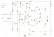
The schematic is just one I found on the internet. It might not be 100% correct, but it should be good enough for you to locate the resistor you are looking for.
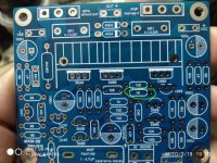
On the picture of your board I have marked the resistor I Think it is. But you need to compare with the schematic and check that it really is the right one. Since I don't have your board, it's hard for me to see exactly which one it is. If you preset the trimmer for 1kohm before mounting it, everything should be normal when powering up. So the risk is minimal. Just be careful the first time you start changing the value. Keep an eye on the bias current. It should be very easy to set and keep stable. If it behaves strange or becomes unstable, then you have chosen the wrong resistor.
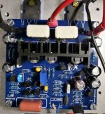
The last picture is just a picture of my board. It's completely different, so it doesn't tell you much. Only that the trimmer can fit on the board, without having to drill any new holes.
Attachments
Hi,
Yes, you should be able to do the same change to your board.
Your board is the new version, mine is the old version. But the amp should be the same. They just changed the layout and some component values.
The schematic is just one I found on the internet. It might not be 100% correct, but it should be good enough for you to locate the resistor you are looking for.
On the picture of your board I have marked the resistor I Think it is. But you need to compare with the schematic and check that it really is the right one. Since I don't have your board, it's hard for me to see exactly which one it is. If you preset the trimmer for 1kohm before mounting it, everything should be normal when powering up. So the risk is minimal. Just be careful the first time you start changing the value. Keep an eye on the bias current. It should be very easy to set and keep stable. If it behaves strange or becomes unstable, then you have chosen the wrong resistor.
The last picture is just a picture of my board. It's completely different, so it doesn't tell you much. Only that the trimmer can fit on the board, without having to drill any new holes.
..thank you very much for your advice and dedicated time for it
Hi,
Yes, you should be able to do the same change to your board.
Your board is the new version, mine is the old version. But the amp should be the same. They just changed the layout and some component values.
The schematic is just one I found on the internet. It might not be 100% correct, but it should be good enough for you to locate the resistor you are looking for.
On the picture of your board I have marked the resistor I Think it is. But you need to compare with the schematic and check that it really is the right one. Since I don't have your board, it's hard for me to see exactly which one it is. If you preset the trimmer for 1kohm before mounting it, everything should be normal when powering up. So the risk is minimal. Just be careful the first time you start changing the value. Keep an eye on the bias current. It should be very easy to set and keep stable. If it behaves strange or becomes unstable, then you have chosen the wrong resistor.
The last picture is just a picture of my board. It's completely different, so it doesn't tell you much. Only that the trimmer can fit on the board, without having to drill any new holes.
... my PCB schematic should be this ..
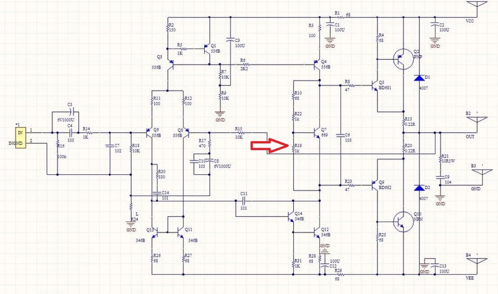
... my PCB schematic should be this ..
And the arrow shows the resistor you need to replace with a 2k trimpot.
Just follow the traces on the pcb, until you locate the correct resistor.
And the arrow shows the resistor you need to replace with a 2k trimpot.
Just follow the traces on the pcb, until you locate the correct resistor.
 thanks
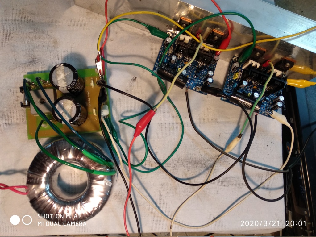
Hello, friends! Has anyone tried this type of power supply for the MX50 SE amplifier? The seller writes that the block is stable. And it is necessary, like, not stabilized? Perhaps there are other suitable options for switching power supplies?
Or is it better to use a classic power supply based on a toroidal transformer?
https://aliexpress.ru/item/32948381172.html?spm=a2g0s.8937460.0.0.77622e0e5VW4N4

Or is it better to use a classic power supply based on a toroidal transformer?
https://aliexpress.ru/item/32948381172.html?spm=a2g0s.8937460.0.0.77622e0e5VW4N4
Last edited:
Hello, friends! Has anyone tried this type of power supply for the MX50 SE amplifier? The seller writes that the block is stable. And it is necessary, like, not stabilized? Perhaps there are other suitable options for switching power supplies?
Or is it better to use a classic power supply based on a toroidal transformer?
https://aliexpress.ru/item/32948381172.html?spm=a2g0s.8937460.0.0.77622e0e5VW4N4
I would combine this type of power supply with class D amplifier ....
- Home
- Amplifiers
- Solid State
- LJM MX50 kit amp