Audio fan, thanks for that link, it's a good read.
AndrewT, your memory was correct, as usual. Well done!
AndrewT, your memory was correct, as usual. Well done!
Those who have tried the "Lead Compensation capacitor" in and out of the Amplifier, care to share their views on the difference it makes?
I have read, but don't understand what "the phase margin is increased at the unity gain point." means.
Also, would increasing C1 or C4/C3 increase the lower midrange?
Thank you,
Ron
I have read, but don't understand what "the phase margin is increased at the unity gain point." means.
Also, would increasing C1 or C4/C3 increase the lower midrange?
Thank you,
Ron
Lead comp.....Those who have tried the "Lead Compensation capacitor" in and out of the Amplifier, care to share their views on the difference it makes?
I have read, but don't understand what "the phase margin is increased at the unity gain point." means.
Also, would increasing C1 or C4/C3 increase the lower midrange?
Thank you,
Ron
You can raise the unity gain crossover point to a higher frequency and
still maintain adequate phase margin ( amp is kept from ringing).
Most say this is less musical (those that have tried it).
All this is for "anal" scientific types .... even my "crippled" sub badger
has a bandwidth of 50K (-3db) , with just a 100pF main VAS compensation
cap - no dual cap TMC. PS- C2 is 680pf on the sub amp.
C1 = input .. increasing it would slightly lower your subsonic (<5hz)
response. C3/C4 the same.
C2 is the HF filter , increasing it will cut/reduce your >50Khz.
Edit - NOTHING will just "cut your midrange" ??? Badger and all my amps are at least
5hz-100Khz flat +/- 1/2db.
OS
Last edited:
the super leach had 800khz gain bandwidth....
And if I remove the input filter on my CFA "ND" , I have 2.85mhz gain bandwidth 😛 .
This is the point where the amp can even amplify ... for those who don't know.
The ND (fastest amp) can amplify 300Khz at the full 27X.
Badger also has 800K GBWP and can approach its 30X+ at 150khz.
But we filter the input anyways to <150khz. All that wasted bandwidth goes
for "bragging rights" 😱
 .
.OS
What is the minimum and maximum gain I should use for the various transistors?
Most of my present 992/1845's are @ 200Hfe. They work in my wolverine-badger
perfect (almost the same circuits).
>400 can be used , the Re's (R15/16 -20/21) could be raised slightly for Q1/2 -5/6 to compensate. BTW - Q5/6 can be low voltage - ksc1815/a1015 , as well.
They just see a few volts. 🙂
OS
Edit - NOTHING will just "cut your midrange" ???
OS
Where did that come from??? I had asked about the effects of C1, C3/4 on the lower midrange frequencys , not how to lower midrange frequency. 😉
Thanks OS, I like my amp and it's working very well, just waiting for the caps to settle. (no flames) I will try different input caps in the stock value, in search of more "soul" to the sound. Now using Russian NOS PETP K73-16. ~20 hours on them.
it's nice to know how "flat" the frequency amplification range is. Thanks for that info.
Ron
Hi Ron,
If you are waiting for your caps to "settle" and add that distortion/coloration that your ears are used to hearing in the music from your old stereo, you may be in for a long wait. You are in true HiFi land now. You are hearing what the sound engineer heard, not what the radio audience is used to hearing. 😉
If you are waiting for your caps to "settle" and add that distortion/coloration that your ears are used to hearing in the music from your old stereo, you may be in for a long wait. You are in true HiFi land now. You are hearing what the sound engineer heard, not what the radio audience is used to hearing. 😉
Hi Terry,
I agree with your enthusiasm on the quality of the Honey Badger.
The Honey Badger is replacing a high quality parts Pass F5.
I felt like it needed a "little more Oomph", my system has Oomph in spades now. 😉
I'm pretty sure I could fry my (Planet 10) redesigned Thor speakers if I wasn't careful.
You have built enough amps to know that different Caps in the power supply can change the sound of an amp, so will the input cap, which is directly in the signal chain.
You were very polite and I hope I've come across the same way.
Ron
Most of my present 992/1845's are @ 200Hfe. They work in my wolverine-badger
perfect (almost the same circuits).
>400 can be used , the Re's (R15/16 -20/21) could be raised slightly for Q1/2 -5/6 to compensate. BTW - Q5/6 can be low voltage - ksc1815/a1015 , as well.
They just see a few volts. 🙂
OS
How "slightly" do the resistors need to be raised in that case?
How "slightly" do the resistors need to be raised in that case?
You would have to scope it to see if you get square wave "overshoot".
OS
Pete,
I'm really enjoying the Honey Badger, thank you for your continued hard work helping us solder monkeys.
Today I tried several different sizes and types of input caps, C1, and didn't really notice any difference. I tried up to an 8.2uF MultiCap. I didn't think I would gain any range but I wanted to hear how several different types caps and/or bypass caps changed the sound. Some detracted by being veiled (clarity cap SA) and other by just blurring (MIT Multicap . I'm sticking with my Russian PETP 2.4uF. Other tried were Obligatto gold, Dayton, Solen. Bypass Westcap PIO, Vitamin Q, Russian F1 Teflon and an OLD green Tropicap. I did this just for fun, wasn't expecting much.
It's nice to hear what these Thor speakers can do, very loud and clean sound. Zero distortion at 5/8 volume, I value my speakers too much to go much higher than that.
Thank you OS!
Ron
Last edited:
Pete,
I'm really enjoying the Honey Badger, thank you for your continued hard work helping us solder monkeys.
Today I tried several different sizes and types of input caps, C1, and didn't really notice any difference. I tried up to an 8.2uF MultiCap. I didn't think I would gain any range but I wanted to hear how several different types caps and/or bypass caps changed the sound. Some detracted by being veiled (clarity cap SA) and other by just blurring (MIT Multicap . I'm sticking with my Russian PETP 2.4uF. Other tried were Obligatto gold, Dayton, Solen. Bypass Westcap PIO, Vitamin Q, Russian F1 Teflon and an OLD green Tropicap. I did this just for fun, wasn't expecting much.
It's nice to hear what these Thor speakers can do, very loud and clean sound. Zero distortion at 5/8 volume, I value my speakers too much to go much higher than that.
Thank you OS!
Ron
Glad to hear some enjoying my "older creation".
I must recommend member Vzaichenko's "21'st century protection board"
http://www.diyaudio.com/forums/solid-state/264313-how-build-21-st-century-protection-board.html
for any Badger amp .
It would nicely co-exist with the specific circuitry and power supplies
that encompass a badger build.
And you would then have "audiophile class" OEM level safety built in.
Plus , your speakers would be absolutely protected.
PS - replaces the softstart (even the ON switch) , SS relay over-current/offset/thermal ...... EVERYTHING !
OS
OS, Thanks for the link! I'll read that when I have a chance tomorrow.
I should mention that the cap I'm using for C1 is the Russian K73-16, BTW, I wasn't looking to color the sound. I was trying different caps to compare the sound and to verify the best sound possible (IMO) through my
speakers.
I do have a soft start and speaker delay w/DC protection inside the case, as was advised by people much smarter than me. My concern is that this AMP has so much power that it might bottom out my drivers, and with tweets $275 a pop, I'm cautious. 😀
Just a solder monkey, with a really good amp.
Ron
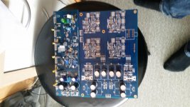
OS,
I have Rev 2.3 of the HB boards (blue) that I am currently assembling. I've noticed numerous places on the board where it appears jumpers are to be installed by a white line on the component side. Is that what they indicate? The reason I ask is, where all of the white lines are the solder pads on the solder side are covered with enamel and hence cannot be solder to. Is this an error on this rev board? Must the enamel be scrapped off first and pad cleaned before soldering? It would appear so, but I find that somewhat hard to believe if that were by design. 😉
I have Rev 2.3 of the HB boards (blue) that I am currently assembling. I've noticed numerous places on the board where it appears jumpers are to be installed by a white line on the component side. Is that what they indicate? The reason I ask is, where all of the white lines are the solder pads on the solder side are covered with enamel and hence cannot be solder to. Is this an error on this rev board? Must the enamel be scrapped off first and pad cleaned before soldering? It would appear so, but I find that somewhat hard to believe if that were by design. 😉
OS,
I have Rev 2.3 of the HB boards (blue) that I am currently assembling. I've noticed numerous places on the board where it appears jumpers are to be installed by a white line on the component side. Is that what they indicate? The reason I ask is, where all of the white lines are the solder pads on the solder side are covered with enamel and hence cannot be solder to. Is this an error on this rev board? Must the enamel be scrapped off first and pad cleaned before soldering? It would appear so, but I find that somewhat hard to believe if that were by design. 😉
Never mind. Got it. Pre-installed.
Those jumpers are through hole double sided (pre-run - no soldering).
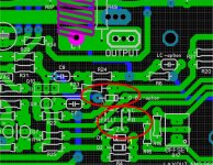
The only changes to make a V2.4 are ...
(below attachment) -
1. the "clip" diode , you would place it between (anode -Q10 collector)
to (Cathode - Q9 base).
2. the screen print for the CRZ options is more verbose. You DO have to scrape
and jumper one of these.
OS
The only changes to make a V2.4 are ...
(below attachment) -
1. the "clip" diode , you would place it between (anode -Q10 collector)
to (Cathode - Q9 base).
2. the screen print for the CRZ options is more verbose. You DO have to scrape
and jumper one of these.
OS
Attachments
- Home
- Amplifiers
- Solid State
- diyAB Amp The "Honey Badger" build thread