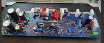
On my fourth board. Built it carefully with some great help from UncleMud.
With first turn on with the DBT in place I got these values at 120ACV:
Both LEDs work
Current across each fuse = 0.430 +/- DCV
R7 is sitting at 8.07DCV
Loop IV = -0.793 DCV
R17 Offset = 005.2 mV
After 15 turns of R30:
Loop 1V moves from -0.795DCV to -1.049DCV
R7 = -08.18DCV
R30 = 00.0 mV
R17 = 7.9mV
I actually pushed R30 to 20 turns, but still no measurable value on R30, but the Loop IV increased to ~ 1.300 DCV
Do I have a bad Pot at R30?
Do I continue to move R30 even though the Loop IV is increasing?
And particular spot to check on the board?
Thanks
I was curious as to why you have C-R bridged, but no R18? Thanks!See photo. I was guided to use this during the first tests and early biasing. Maybe I misconstrued the input.
As you can see, I'm stuck at this point.
Dave, I was curious as to what method of cascode you used. If it was the zener, what value for R19 did you use? Thanks!Hello Forum Members,
I am happy to report that another Honey Badger has been born! I hit the power switch this morning and felt greatly relieved that everything seemed to power up as expected.
Dave,
Thanks for your quick reply. I had already went with the zener option and the R19 value of 68K, as listed in the BG. However, some here have stated issues with that, and suggested using 15K/1W, instead (option 1). I was hoping you might have went with the zener option, given your recent success. I think I'll switch R19 out for the 15K/1W as suggested in 2.5.4, unless someone else has some more input.
Thanks again!

I was using TP1 and TP2. Guess that is incorrect.When you say 0V on R30, where are you measuring this? It should be on R34 and R35.
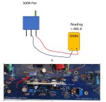
Speaking of the R30 Pot, see illustration below. I want to make sure I've set the R30 trimmer pot regarding the position of the pot on the board and the right side reading 485.0 ohms. Is this correct or reversed? The guide says set pot to maximum resistance [500R].
Attachments
Chiptech,
Take an impedance measurement in ohms using your DMM. Measure from Pin 1 (Emitter) to Pin 3 (Base) of your Q13 NPN transistor.What is the value it measures? It should be at least 1100 ohms since it is measuring R29 (which is 680 ohms) and R30 pot (which should be set close to 500 ohms) in series.


Best,
Anand.
Take an impedance measurement in ohms using your DMM. Measure from Pin 1 (Emitter) to Pin 3 (Base) of your Q13 NPN transistor.What is the value it measures? It should be at least 1100 ohms since it is measuring R29 (which is 680 ohms) and R30 pot (which should be set close to 500 ohms) in series.
Best,
Anand.
- Home
- Amplifiers
- Solid State
- diyAB Amp The "Honey Badger" build thread