...But the power supply.
Eww, that is one of the most important part of an amplifier, especially this topology

. . . and I think my new supply will be a mix of chokes & cap multiplier
Can you teach me how to design a proper choke supply? I had a feeling that it should be done through measurement, no?
My experience is that we cannot just throw any values and hope nothing to loose. Actually wrong values will degrade the sound (because we increased the impedance already). Trial and error is very tedious.
Say I have some coils that I can use for this purpose. I have the tool to measure the inductance. Then I need the correct capacitance, right? If I do it simply using LTSpice, what parameters that I need to watch out in order to know that the filter will work? Same as general solid state power supply design?
choke value and current draw are the inter-related factors. Not choke & capacitance.
Then I cannot just pick any off-the-shelf choke?
Hi Jay,
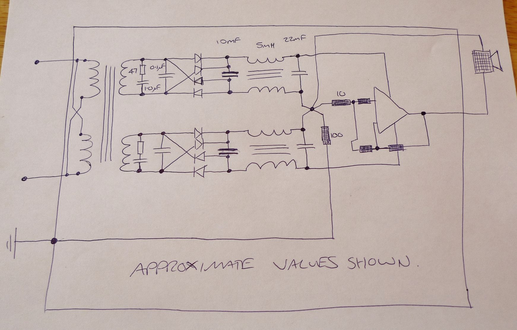
I began my experiment with choke regulation by going for simple full choke regulation ( Luddite tendencies ) but now I am thinking of letting the chokes deal with only VHF and letting more conventional regulation deal with the audio frequencies. I think this will give best overall AC & DC regulation but having said that I am very satisfied with the subjective performance of full choke regulation. I recommend chokes in all power lines from the transformers.
I always design my supplies in spice but didn't have much success with transformers & inductors in LT spice.
Two things have to be considered - how the supply behaves in use & how it behaves during turn on. These two factors can pull in opposite directions and so we have to balance between them.
If the overall DC resistance of transformer & choke is too low the supply can ring & go over voltage during turn on. If there is too much DC resistance the voltage will drop too much during loud passages. The tendency for ringing can be reduced by having the cap after the choke larger than cap before the choke.
This is a reasonable starting point for Full choke regulation:
http://www.diyaudio.com/forums/atta...7114-simple-symetrical-amplifier-p1020970.jpg
each coil perhaps 0.1R
I use the secondaries of regular EI transformers as chokes and they work just fine.
The DC polarization will mean the effective inductance is less than measured inductance - but you can make allowances for that.
But if you would like to PM me your detailed criteria I will check out something in spice and optimize it for you.
Last edited:
I always design my supplies in spice but didn't have much success with transformers & inductors in LT spice..
That's in line with my intuition.
If the overall DC resistance of transformer & choke is too low the supply can ring & go over voltage during turn on. If there is too much DC resistance the voltage will drop too much during loud passages. The tendency for ringing can be reduced by having the cap after the choke larger than cap before the choke.
Okay, noted. I'm not sure tho that for practical reason the DCR can be too low. Aren't low DCR choke expensive. I have seen and used low DCR air-core but that is I think overkill (if proven very effective, no problem tho).
This is a reasonable starting point for Full choke regulation:
http://www.diyaudio.com/forums/atta...7114-simple-symetrical-amplifier-p1020970.jpg.
Thanks, I will read that later. I have tried many references in the past, but couldn't learn anything and just took the shortcut: trial and error by ears
I use the secondaries of regular EI transformers as chokes and they work just fine.
I have many big choke transformers that I want to use. If necessary I can use audio output transformers (very big tho).
But if you would like to PM me your detailed criteria I will check out something in spice and optimize it for you.
Thank you very much but I don't know yet where to start (and may still be a long way to go). I have noted your approach to separate system ground from transformer secondary with chokes. I have done the same thing but there is one other approach that I like to do. It is more like EMI filter. I install the CLC directly after the secondary, so before the rectifiers.
The other CLC (with big caps) I used to do is after the rectifier, usually before a cap multiplier. Class-A amps of course, like my TSSA.
If you put the chokes before the diodes the resultant PSU internal impedance is very high so this kind of regulation is only suitable full class A which needs constant current.
Chokes after the diodes is much lower internal impedance so is suitable for Class AB & Class A.
Chokes after the diodes is much lower internal impedance so is suitable for Class AB & Class A.
... That you can reduce to one, adding a soft start circuit.Two things have to be considered - how the supply behaves in use & how it behaves during turn on. .
One of the rare things i agree with audiophiles blind beliefs is the benefit to overkill the PSU current.
My 1100VA transformer +big caps are affraying, if directly plugged in sector: The Lights flicker in my home, and the noise in the transformer terrorize my dog
With soft start, everything runs smoothly, and i can hear my caps's thanks and look at their smiles during much more years.
Christophe, your bias spreader in your CFB Crescendo is 220 Ohm and when you bias the output correctly it will be even less. Your cascode VAS has a current output and the bias spreader will convert that into a voltage. In that sense you have a voltage drive due to Ohms law U = I x R so you could say you make an I/U conversion and current and voltage is interchangeable due to that formula as long as the VAS does not go out of steam current wise. The bias spreader resistor then forms a low pass with the input capaciatnce of the output stage. The lower the driving resistance the better you control the input capacitance of you MosFet output stage. On the other hand you have to roll off the open loop gain somewhere. In my preamp that is also a small lateral mosfet current feedback power amp with 2W class A i simply use the gate stoppers for that to form a low pass. The gate stoppers are arranged in such a way that the gate stopper to the P-Channel is somewhat smaller in value. I have not tried a miller cap or other options but it works just fine.
To L. C., (Please comment ?) I'd like to see an improved SSA BIGBT HP's PSU for the following reasons:
I prefer a single power supply (when it is possible) for the both (or more) channels (as opposite to audiophiles) for the stereo localization (i explained it earlier).
If it is impossible, by example in my muti-ways active speakers, i prefer to use the same supply for all the channels (coherency of bass and treeble during big transients, same player shoot again).
For all those reason, i will prefer a PSU separated from the amp board.
Unless the rails are so perfectly regulated or stabilized, that you can forget about that, and enjoy the short wires low self.
Even here, i would prefer a single transformer, preferably a C core one with shield between the primaries and secondaries coils, to get no capacitive coupling between them , in order to minimize hf leakages between them.
I always use a ferrite on the power cord, (in fact on all the cords, including signal) and a HF rejection filter in the AC plug too.
Christophe, your bias spreader in your CFB Crescendo is 220 Ohm and when you bias the output correctly it will be even less. Your cascode VAS has a current output and the bias spreader will convert that into a voltage. In that sense you have a voltage drive due to Ohms law U = I x R so you could say you make an I/U conversion and current and voltage is interchangeable due to that formula as long as the VAS does not go out of steam current wise. The bias spreader resistor then forms a low pass with the input capaciatnce of the output stage. The lower the driving resistance the better you control the input capacitance of you MosFet output stage. On the other hand you have to roll off the open loop gain somewhere. In my preamp that is also a small lateral mosfet current feedback power amp with 2W class A i simply use the gate stoppers for that to form a low pass. The gate stoppers are arranged in such a way that the gate stopper to the P-Channel is somewhat smaller in value. I have not tried a miller cap or other options but it works just fine.
My simulation shows 70 ohm.
dado
Then the VAS needs ample current drive capability.
VAS runs at 13.5 mA in my simulation.
dado
Attachments
... That you can reduce to one, adding a soft start circuit.
One of the rare things i agree with audiophiles blind beliefs is the benefit to overkill the PSU current.
My 1100VA transformer +big caps are affraying, if directly plugged in sector: The Lights flicker in my home, and the noise in the transformer terrorize my dog
With soft start, everything runs smoothly, and i can hear my caps's thanks and look at their smiles during much more years.
Yes, a soft start would mean that potential resonances would not be excited at turn on and turn on would be less violent but I would still recommend that the choke regulation scheme is designed with sufficient damping so that there is not even a tendency for ringing. An underdamped scheme could give rise to the kind of oscillation problems that jayadev was referring to in the other thread.
I have the feeling Christophe that you regard me as an audiophile that likes to see hifi as mythical art that lies outside the realm of the physical sciences - actually nothing could be further from the truth. When I hear a comment like "valve circuits add some magic to the sound" it annoys me that some adopt this religious kind of an approach - my immediate question is what are the factors that are responsible for this perception ?
I always intend to follow good engineering principals when designing audio but I also accept that there are some things that might be very difficult to measure that we can hear subjectively so I allow my ears to inform my choices also.
I agree on that, of course. Just i do not agree this use of gate stopper as a low pass filter because gate capacitance is not dynamically linear.Christophe, your bias spreader in your CFB Crescendo is 220 Ohm and when you bias the output correctly it will be even less. Your cascode VAS has a current output and the bias spreader will convert that into a voltage. In that sense you have a voltage drive due to Ohms law U = I x R so you could say you make an I/U conversion and current and voltage is interchangeable due to that formula as long as the VAS does not go out of steam current wise. The bias spreader resistor then forms a low pass with the input capaciatnce of the output stage. The lower the driving resistance the better you control the input capacitance of you MosFet output stage. On the other hand you have to roll off the open loop gain somewhere. In my preamp that is also a small lateral mosfet current feedback power amp with 2W class A i simply use the gate stoppers for that to form a low pass. The gate stoppers are arranged in such a way that the gate stopper to the P-Channel is somewhat smaller in value. I have not tried a miller cap or other options but it works just fine.
Well, using 3 power FETs by rail would help a little to move the capacitance hole a little further out of the range, but that is not fully satisfying on an intellectual point of view.
Many DIYers had oscillations or overshoots problems, when they tried this amp, and i would not like to provide support
Mine is OK after tuning, and sound well enough (the feedback work well enough to compensate the non linearities), so it will stay as-it, i'm a Lazy Dog.
This Crescendo was just a quick'n dirty mod, and, as i'm not so sure that spending a lot of time to improve the driver stage will change the sound in a drastic way. I prefer to spend this time listening music
Again, this was just an example to demonstrate 3 things:
- How most of classical VFB amp can be modified in SSA, and tribute to this so clever symmetrical feedback returns, compensating the emitters offsets.
- How Current feedback can improve both numbers and listening pleasure.
- How Lazy Cat is a talented audio designer.
Looking deeply in the SSA details, my conclusion was that it is so nicely designed and accurately calculated everywhere that, if i had to build a new amp, i would not even try to calculate or simulate anything anymore: Just i would build-it as it, saving time and efforts. I'm not able to do better. And i have never seen a better amp elsewhere.
Oh, my goodness, not at all, and same for most of the SSA threads contributors, experienced and nice fellows.I have the feeling Christophe that you regard me as an audiophile that likes to see hifi as mythical art that lies outside the realm of the physical sciences - actually nothing could be further from the truth. ...
We are not on the Blowtorsh thread
It was just a general smiley/joke, never thougt at you in this manner, far from that.
To L. C., (Please comment ?) I'd like to see an improved SSA BIGBT HP's PSU for the following reasons:
I prefer a single power supply (when it is possible) for the both (or more) channels (as opposite to audiophiles) for the stereo localization (i explained it earlier).
If it is impossible, by example in my muti-ways active speakers, i prefer to use the same supply for all the channels (coherency of bass and treeble during big transients, same player shoot again).
For all those reason, i will prefer a PSU separated from the amp board.
Unless the rails are so perfectly regulated or stabilized, that you can forget about that, and enjoy the short wires low self.
Even here, i would prefer a single transformer, preferably a C core one with shield between the primaries and secondaries coils, to get no capacitive coupling between them , in order to minimize hf leakages between them.
I always use a ferrite on the power cord, (in fact on all the cords, including signal) and a HF rejection filter in the AC plug too.
Hi Christophe

All what you're telling us is so logical in explanations that I believe you, especially because I know you tested all these combinations practically on a real word circuits in familiar system.
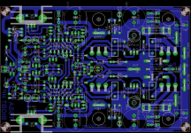
I also had some amps, one very dear to me is still in my possession, named StereoLith. This has separate power supply formed by two toroids, one for the front-end another for the output, a lot of capacitance present, amps PCB-s having regulated rails for front-end, etc. But still it can not come even near to SSA BIGBT CCS's sound quality. Major responsibility for SQ lies in topology, parts, PCB layout and of course in PSU too. In SSA I follow the rule that everything is near to each other as possible, main caps to output BJT-s, etc. Also I like very compact PCB-s where's all onboard except toroid and I just did it that way. So far I have no complaints, it serves its purpose well, sounding well too, so mission accomplished successfully.
Regarding dual mono concept, I'm sure there's so little differences between channels that phase differences do not play significant role, also listening shows no worse stereo imaging than solid stereo amp, on contrary, to mine opinion it is even better.
Currently I'm preparing something even more compact than SSA, to be released soon, even before CSA BIGBT, you'll be surprised too hehe.

- Home
- Amplifiers
- Solid State
- TSSA - The Simplest Symmetrical Amplifier