You're right Alex ") regarding the values at individual junctions.
regarding the values at individual junctions.
However, I was addressing measurements of main parameters: frequency response, bandwidth, phase shift etc. I have made measurements of several LJM amplifiers but have erased all the results afterwards. Now I am tempted to re-install L12-2 and repeat my measurements.
As far as I can recall, THD+N measurements were consistent with these published here but not so low as was claimed elsewhere. There were some results that could explain some shortcomings. There were issues with square wave response at low frequencies, if I recall properly.
Eventually, I will get back with my results within a week or so.
regarding the values at individual junctions.However, I was addressing measurements of main parameters: frequency response, bandwidth, phase shift etc. I have made measurements of several LJM amplifiers but have erased all the results afterwards. Now I am tempted to re-install L12-2 and repeat my measurements.
As far as I can recall, THD+N measurements were consistent with these published here but not so low as was claimed elsewhere. There were some results that could explain some shortcomings. There were issues with square wave response at low frequencies, if I recall properly.
Eventually, I will get back with my results within a week or so.
Welcome to the club!I personally am not at all concerned with distortion while I'm concerned with the amp blowing
But, however this can be frustruating, solving practical problems is a great oportunity to learn how to deal with blown amplifiers.
I have started with DarTzeel NHB-108 clone, then switched to much more promising Acuphase A60 clone. This is I continue to study and develop because results are overwhelming. In the meantime I have studdied these "blameless" midgets. I took them as Devices Under Test to learn how to meassure.
Meanwhile, I've learned a lot but now I hope that within a year I might understand main principles of amplification.
My present preoccupation is building good chassis from thick aluminium plates. That costs and is time consuming, but results are great. Success is always great thing.
Have a pleasant evening Alex.
PS: Michael Beeny, Newzealander from Youtube has also reported that his beloved L12-2 has blown from just touching input ground with finger. They are just blowing.
Last edited:
Hi,
could You supply for a link?
All I found in his vids was a problem with a pre-module in an amp with L12/2 modules in.
I couldn't find a vid reporting a blown amp-module.
Up till 2 months ago Mr. Beeny still praised the L12/2.
Regarding the claimed LF square wave response issues ... did You take into account the highpass characteristic due to the lytic cap in the feedback path?
jauu
Calvin
Hi Calvin,
I"ve tried very hard to find that short passage in a number of recent Michaels' videos ranging in size from 5 to 30 minutes and have found how difficult that can be. "Die Nadelsuche im Heuhaufen" is the best way to describe my attempt. Very hard, but it is somewhere there.
But never mind, if I find it I will post a link to that.
Meanwhile, I have decided to re-install my L12-2 and reproduce meassurements that indicate certain difficulties with low frequency response.
Regards
But, wait a minute.
The best place to visit for those interrested i l12-2 is:
Michael Beeney Channel at Youtube. <= Click here for more
This is perhaps the best place on the web for DIYers interrested in these Chinese midgets. The guy is awesome indeed,: he is a gentleman from "Down Under" who speaks about the subjects we deal with and he does it in the best possible way. Enjoy.
Hello,
I'm considering getting this amp from JOJOHIFI on Aliexpress. They sell V4. Got a few questions, if you don't mind I will of course be adding trimmers for quiescent current fine-tuning.
1) I see some suggest replacing the input signal electrolytic cap with film ones. But 33 μF film caps are HUGE. And the feedback cap is 1000 μF! Am I misunderstanding something? Can I use a smaller value?
Others remove the input cap entirely, is that a good idea?
2) Some people talked about the value of the large white resistors. Mine are all 0.1 Ω. Should I consider lower value ones?
3) The trio of smaller 649/669 transistors are supposed to be thermally coupled and not reside on the main heatsink, I got that. Does it make sense to add a small Aluminium plate so they can at least dissipate heat a bit better than bolting them directly to th PCB?
4) I want to be able to bridge two L12-2. The second amp needs an inverted input, which I should be able to get from the first amp (if i understand this article) correctly. But I can't figure out how/where exactly. Any clues?
5) I'm going to add some speaker protection (DC and startup pop protection). Are there any other protections that would be sensible? Overcurrent protection, is that possible? Fuses maybe? Should I fuse the voltage rails or the speaker wires?
6) Any other components that could/should be replaced with higher-quality ones?
Thanks for your help!
I'm considering getting this amp from JOJOHIFI on Aliexpress. They sell V4. Got a few questions, if you don't mind
I will of course be adding trimmers for quiescent current fine-tuning.1) I see some suggest replacing the input signal electrolytic cap with film ones. But 33 μF film caps are HUGE. And the feedback cap is 1000 μF! Am I misunderstanding something? Can I use a smaller value?
Others remove the input cap entirely, is that a good idea?
2) Some people talked about the value of the large white resistors. Mine are all 0.1 Ω. Should I consider lower value ones?
3) The trio of smaller 649/669 transistors are supposed to be thermally coupled and not reside on the main heatsink, I got that. Does it make sense to add a small Aluminium plate so they can at least dissipate heat a bit better than bolting them directly to th PCB?
4) I want to be able to bridge two L12-2. The second amp needs an inverted input, which I should be able to get from the first amp (if i understand this article) correctly. But I can't figure out how/where exactly. Any clues?
5) I'm going to add some speaker protection (DC and startup pop protection). Are there any other protections that would be sensible? Overcurrent protection, is that possible? Fuses maybe? Should I fuse the voltage rails or the speaker wires?
6) Any other components that could/should be replaced with higher-quality ones?
Thanks for your help!
Last edited:
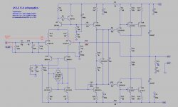
Is this correct for the "slave" amp in a bridged configuration? I'm going by this article.
Changes in red. The old input is removed and grounded. The new input is coming from the amplified
Thanks!
Changes in red. The old input is removed and grounded. The new input is coming from the amplified
out pin of the "master" amp, goes through R_BR (same value as the feedback resistor circled red, 10k) directly into the feedback of the slave.Thanks!
Attachments
On my pair of boards the feedback cap C8 is also 1000uF, which I feel is too high, so I will probably put in the original circuit's 220uF there. (C8 is also 220uF on Calvin's schema.)1) I see some suggest replacing the input signal electrolytic cap with film ones. But 33 μF film caps are HUGE. And the feedback cap is 1000 μF! Am I misunderstanding something? Can I use a smaller value?
Hi,
well, both schemata I have drawn They simply show different revisions as well as my personal mods to rev_3 (iIrc).
Seemingly a majority of users rely on and use them now .... even Mr. Beeny in his vid -only refferring to them as 'find it somewhere on the internet',
Good to see that I finally did something helpful
jauu
Calvin
well, both schemata I have drawn
They simply show different revisions as well as my personal mods to rev_3 (iIrc).Seemingly a majority of users rely on and use them now .... even Mr. Beeny in his vid -only refferring to them as 'find it somewhere on the internet',
Good to see that I finally did something helpful
jauu
Calvin
That would work, I would personally add LPF and HPF on the new (neg) input.Is this correct for the "slave" amp in a bridged configuration? I'm going by this article.
Changes in red. The old input is removed and grounded. The new input is coming from the amplifiedoutpin of the "master" amp, goes throughR_BR(same value as the feedback resistor circled red, 10k) directly into the feedback of the slave.
Thanks!
hi,Hi,
why? the incoming signal is already HP and LP-filtered coming from the first amp.
jauu
Calvin
You are correct on that, no need to filter. (again)
Thanks! I just hope bridging isn't gong to blow em up. I don't need insane amounts of power, but I have a beefy power supply that a single amp simply can't make full use of.That would work
Maybe paralleling two amps would be more sensible? Would this work? Are the 0.1 Ω resistors enough to avoid oscillations?
Thanks Calvin. Since I'm expecting 4 Ω loads, parallel would probaly be more sensible. I'm still concerned that the 0.1 Ω output resistors might not suffice tho...
And thanks for the schematics! btw, I think I found a mistake. In your L12-2 V.4 schematics, you changed C4 and C6 to 10μ. However, my (blue) VER4 board is silkscreened
I was also surprised to find a Rubycon MCZ for the 1000μ feedback attenuator in my kit (C8). Likely to be a fake?
And I'm scratching my head at your suggestion to add film caps in parallel to C5. Doesn't the original cap have to be removed to get rid of its nonlinearities?
Cheers!
And thanks for the schematics! btw, I think I found a mistake. In your L12-2 V.4 schematics, you changed C4 and C6 to 10μ. However, my (blue) VER4 board is silkscreened
105 for 1μ and came with 1μ caps (look like small unpolarized electrolytics).I was also surprised to find a Rubycon MCZ for the 1000μ feedback attenuator in my kit (C8). Likely to be a fake?
And I'm scratching my head at your suggestion to add film caps in parallel to C5. Doesn't the original cap have to be removed to get rid of its nonlinearities?
Cheers!
Hi,
when paralleling either Transistors or complete amps one needs to either match tightly or use balancing resistors (here: emitter resistors or output series resistors).
For every so small difference in output the second amp would otherwise appear almost like a dead short to the first amp.
To check if the amps stay within their SOA in bridged mode just calculate the required minimum supply voltages and current.
Say the supply lines are ~+-30V.
That's good for ~100W@4R (+-28Vpp -> 20Vrms).
The load then draws 5Arms, +-7App.
In bridged mode each amp would work into a 2R load, hence the current would double to 10Arms, +-14App.
Since the voltage across the load and the current through the load double each, the power quadruples.
Due to supply lines giving in, losses, etc. the practical figure is rather only 3x the power.
Calculating with 150W@2R per amp it requires ~18Vrms and ~8.5Arms (+-24Vpp and +-12.5App).
Since of each amp only one of the two output pairs (either the NPNs or the PNPs) drives the load, the current through the single transistor is half that value, hence between 6A and 7A.
The chosen transistors should be able to drive such amounts of current for short periods with still some headroom left.
jauu
Calvin
ps. thanks for the 105 hint
Adding a film to a lytic .... was just for my good gut feelings.
Actually I'm quite convinced that even those claiming the loudest about cap sound fail spectacularly when they don't know.
I'm still waiting for just one single person to step forward and proof to the world that he can distinguish with blinded eyes between 10 different setups if they utilize (coupling) caps, which type of caps and possibly what brand
Thanks again Calvin for your time!
How did you arrive at 100W? +-30Vac*sqrt(2) gives me +-42Vdc. That's 10.6A or 450W @ 4Ω. That can't be right. Where's my mistake?
My transformers are closer to 35Vac, which would raise the power to over 600W - per amp! That can't be right.
For that DC-blocking cap I'm currently looking at a Wima MKS4 33μF. It's Polyester instead of Polypropylene, but should still be better than electrolytics and is still affordable.
Say the supply lines are ~+-30V. That's good for ~100W@4R (+-28Vpp -> 20Vrms).
How did you arrive at 100W? +-30Vac*sqrt(2) gives me +-42Vdc. That's 10.6A or 450W @ 4Ω. That can't be right. Where's my mistake?
My transformers are closer to 35Vac, which would raise the power to over 600W - per amp! That can't be right.
For that DC-blocking cap I'm currently looking at a Wima MKS4 33μF. It's Polyester instead of Polypropylene, but should still be better than electrolytics and is still affordable.
This guy looks promising:...
I'm still waiting for just one single person to step forward and proof to the world that he can distinguish with blinded eyes between 10 different setups if they utilize (coupling) caps, which type of caps and possibly what brand
Last edited:
- Home
- Amplifiers
- Solid State
- L12-2 CFP Output amp 120W*2 8R