That is not a strange result since the KSC3503 has higher Early voltage which makes it a better current source. The 2SC4793 might work even better. Medium power transistors often have very high Early voltage.
Small-signal transistors often have low Early voltage, especially if they are primarily for switching use. The KSC1845 and BC550C are reasonably high but you can find better if you want high Early voltage.
Small-signal transistors often have low Early voltage, especially if they are primarily for switching use. The KSC1845 and BC550C are reasonably high but you can find better if you want high Early voltage.
I know the goal of a baker clamp in itself, but I don't know what the goal of it is in the circuit on the bench. Is there some observed behavior which has led to a failure or some undesirable behavior?
If not then we don't really know what to do about a problem we haven't identified.
under normal music listening, probably nothing....
but try to short the output of the amp for a couple of seconds with music signal present, see how things change so fast.....
some designs i think has mitigating measures built in, Leach did it with his amps....for that eventuality that no one wants and much less anticipated...
this is the reason we had the honey badger redesigned for on board SOA protection...
there are even plans to convert this design to class H...
Attachments
Last edited:
I would try a resistor at the emitter of the cascode transistor which sets a maximum current according to the cascode voltage. A 56ohm resistor at the emitter of Q12 here would do it:
diyAB Amp - The "Honey Badger"
diyAB Amp - The "Honey Badger"
The question was about how to clamp the VAS. The resistor will limit the VAS current. This is only useful if the output stage is SOA limited, which will protect against a short.
i see a lot designs heralding ppm distortions....
i would like to see a lot more designs that do not have turn on turnoff thumps, and can survive a dead short on the speaker jacks indefinitely...
wishful thinking?
Talking about current sources, what bias current do you guys use through 1) the 1N4148 diodes and 2) LED (green) or whatever u might be using.?
Thanks
not sure i am getting you, 2.... leds are biased depending on color, the blue led has the lowest bias current, about ten times that of red or green...1...1n4148 is just a few mA of forward bias....
Tony I meant, the bias current for green LEDs could range from 1mA to 20mA. I'm asking what bias current the designers here use for their LEDs that are used in the bias circuit of a constant current source. Here the LEDs are used for their forward voltage and not the light they produce. And what specific current they use for there 1n4148 since this bias current could make a difference in THD, rail sticking, square wave response? Or is this trivial and makes no difference, and any arbitrary value is sufficient?
Tony I meant, the bias current for green LEDs could range from 1mA to 20mA. I'm asking what bias current the designers here use for their LEDs that are used in the bias circuit of a constant current source. Here the LEDs are used for their forward voltage and not the light they produce. And what specific current they use for there 1n4148 since this bias current could make a difference in THD, rail sticking, square wave response? Or is this trivial and makes no difference, and any arbitrary value is sufficient?
i am not sure there are hard and fast rules, it is a designer's choice....
i see a lot designs heralding ppm distortions....
i would like to see a lot more designs that do not have turn on turnoff thumps, and can survive a dead short on the speaker jacks indefinitely...
wishful thinking?
For most amps you could request a SOA limiter and VAS clamp and that would take care of the short issue. Someone might be willing to finish the design. Thump could probably be reduced but not eliminated in most amps if the designer had not already considered it.
Tony I meant, the bias current for green LEDs could range from 1mA to 20mA. I'm asking what bias current the designers here use for their LEDs that are used in the bias circuit of a constant current source. Here the LEDs are used for their forward voltage and not the light they produce. And what specific current they use for there 1n4148 since this bias current could make a difference in THD, rail sticking, square wave response? Or is this trivial and makes no difference, and any arbitrary value is sufficient?
If you are designing an amp you can find all that out yourself through testing. It usually turns out to matter very little as long as the LED current is in the same ballpark as the CCS current. Usually you have the freedom to set the LED brightness the way you want, or you may just decide to use a large feeder resistor just so you don't need a 1W resistor just to feed an LED.
The emitter resistor of the CCS makes it very tolerant of the bias of the LED. Since the LED dynamic resistance is proportional to bias current, feeder resistor value doesn't have much effect on PSRR although there is a penalty that rises as current increases due to the LED parasitic resistance.
Also - consider any led used to reference a CCS/cascode will add (or subtract)
it's thermal co-efficient in the circuit.
I judiciously use red/green /or blue to this end.
For example , the typical red led nearly negates the bipolar tempco in a CCS.
Forward current of the reference would also affect tempco.
OS
it's thermal co-efficient in the circuit.
I judiciously use red/green /or blue to this end.
For example , the typical red led nearly negates the bipolar tempco in a CCS.
Forward current of the reference would also affect tempco.
OS
Clamping ???
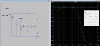
I have noticed on Badger V2 , the cascode in the design seems to not only clip
perfectly , but the diode type (model) does not add THD short of clipping ?
Any diode - no difference. Higher Z of the cascode ? ... All I know is
the clipping response is symmetrical and perfect. Perhaps KT can shed
light on why ???
PS - I was about to get anal with an active clamp - the single diode (D3)
exceeded expectations. :")
OS
I have noticed on Badger V2 , the cascode in the design seems to not only clip
perfectly , but the diode type (model) does not add THD short of clipping ?
Any diode - no difference. Higher Z of the cascode ? ... All I know is
the clipping response is symmetrical and perfect. Perhaps KT can shed
light on why ???
PS - I was about to get anal with an active clamp - the single diode (D3)
exceeded expectations. :
OS
Attachments
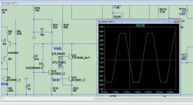
There is a phase inversion when the VAS clips which causes the jagged edge. A collector junction will saturate and then you will notice that the VAS input voltage tracks the VAS output voltage. This is positive feedback.
When it leaves clipping it passes through the region of positive feedback again, so the output shoots up and back down wildly causing a spike.
The reason there is never outright oscillation is because the time constant of the positive feedback reaches to DC so there is no frequency at which to oscillate.
During clipping the VAS voltage gain is determined by the voltage drop across the VAS emitter resistor. Since the buffer transistor multiplies the current available to R20, it dramatically increases the positive feedback available during clipping.
There are 2 solutions. We can prevent any possibility of positive feedback in the first place (complex clamp), or we can just reduce the amount of positive feedback to the point where it is irrelevant (D3, baker clamp, etc).
Clamping needs to activate at the right VAS output voltage to be effective. Cascodes and buffers and various things will shift that point up or down. For instance a cascode may saturate before the VAS output drops below the base voltage of the buffer transistor, causing the diode to activate late. This does not always interfere with operation but it does mean that for a brief period before hard clipping the VAS node is loaded by R18 or whatever else is feeding the VAS.
The distortion caused by D3 is just a function of it's saturation current, breakdown leakage current and nonlinear capacitance and does not interact with the VAS parameters.
Last edited:
- Home
- Amplifiers
- Solid State
- diyAB Amp - The "Honey Badger"