In the schematic I downloaded RE was 68 ohms. That was Ostripper's schematic, not yours. I could not see the value you used so I assumed it was the same. My mistake.
And what I said was that RE was equivalent to 2 base stoppers of double it's value which is correct in itself. I did not say that RE+re'+RB was equivalent to 2 base stoppers of etc etc. This is because re' is just a small fraction of the total value in this case and not worth fussing about even though it adds a bit to the equivalent base stoppers when considered. And you already bypassed the existing base stoppers so I have no reason to add them to the result.
And what I said was that RE was equivalent to 2 base stoppers of double it's value which is correct in itself. I did not say that RE+re'+RB was equivalent to 2 base stoppers of etc etc. This is because re' is just a small fraction of the total value in this case and not worth fussing about even though it adds a bit to the equivalent base stoppers when considered. And you already bypassed the existing base stoppers so I have no reason to add them to the result.
In the schematic I downloaded RE was 68 ohms. That was Ostripper's schematic, not yours. I could not see the value you used so I assumed it was the same. My mistake.
And what I said was that RE was equivalent to 2 base stoppers of double it's value which is correct in itself. I did not say that RE+re'+RB was equivalent to 2 base stoppers of etc etc. This is because re' is just a small fraction of the total value in this case and not worth fussing about even though it adds a bit to the equivalent base stoppers when considered. And you already bypassed the existing base stoppers so I have no reason to add them to the result.
Yes OS had R27 as 68 ohms in the build guild showing V1.0 schematic. There is also a OS schematic V2.4 that I copied only in a attempt to make clearer. Isn't R27 the resistor for the VAS current source. Isn't R23 the VAS emitter resistor with a value of 47 ohms both in my version schematic 2.5.4 and OS version 2.4 ?
Last edited:
Let's try not to talk about 3 schematics at once.
So you are correct that we have re'=3ohm and RE=47ohm, and thus re'+RE=50ohm.
The problem is that this resistance is feeding both bases at once, whereas the base stoppers are only feeding one base each. If you were to put those base stoppers in parallel as if they were one resistor feeding both bases then it would be an 11 ohm resistor. The VAS resistance is similarly feeding both bases at once so we need to do the opposite and split it into two resistances to get the equivalent circuit for individual base stoppers. So our 50 ohm VAS is like individual 100 ohm base stoppers. The 22ohm resistors bring up our effective resistance per base to 122 ohms.
And this is of course only at RF where the miller capacitor connects the VAS collector to it's base.
If re' equals Vt/Ic and the VAS current is about 9mA we get 26/9 which equals approximately 3 ohms add that to RE of 47 and we get 50 then add the base stopper resistance of 22 and we get 77 ohms. What am I missing?
So you are correct that we have re'=3ohm and RE=47ohm, and thus re'+RE=50ohm.
The problem is that this resistance is feeding both bases at once, whereas the base stoppers are only feeding one base each. If you were to put those base stoppers in parallel as if they were one resistor feeding both bases then it would be an 11 ohm resistor. The VAS resistance is similarly feeding both bases at once so we need to do the opposite and split it into two resistances to get the equivalent circuit for individual base stoppers. So our 50 ohm VAS is like individual 100 ohm base stoppers. The 22ohm resistors bring up our effective resistance per base to 122 ohms.
And this is of course only at RF where the miller capacitor connects the VAS collector to it's base.
Let's try not to talk about 3 schematics at once.
So you are correct that we have re'=3ohm and RE=47ohm, and thus re'+RE=50ohm.
The problem is that this resistance is feeding both bases at once, whereas the base stoppers are only feeding one base each. If you were to put those base stoppers in parallel as if they were one resistor feeding both bases then it would be an 11 ohm resistor. The VAS resistance is similarly feeding both bases at once so we need to do the opposite and split it into two resistances to get the equivalent circuit for individual base stoppers. So our 50 ohm VAS is like individual 100 ohm base stoppers. The 22ohm resistors bring up our effective resistance per base to 122 ohms.
And this is of course only at RF where the miller capacitor connects the VAS collector to it's base.
Thanks for clearing that up and the extra explanation. It make perfect sense now with no ambiguity.
I am just about to do some testing.
I have.
1. Shorted out the base stoppers R34/35.
2. Changed R23 to 4.7 ohms (Initial test)
3. Changed R22 from 820 to 470 to maintain the same current through Q9.
I am planning to build the badger and so i am studying the schematic.
I have a doubt related with the tail resistor between the LTP and it's ccs.
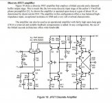
I am talking about R14 (2k2 ohm) in the schematic below.
Apart from lowering the voltage seen by Q7 what is it used for ?
Does it not slow down the ccs ?
I have a doubt related with the tail resistor between the LTP and it's ccs.
I am talking about R14 (2k2 ohm) in the schematic below.
Apart from lowering the voltage seen by Q7 what is it used for ?
Does it not slow down the ccs ?
Attachments
The question has been asked before with no clear answer.I am planning to build the badger and so i am studying the schematic.
I have a doubt related with the tail resistor between the LTP and it's ccs.
I am talking about R14 (2k2 ohm) in the schematic below.
Apart from lowering the voltage seen by Q7 what is it used for ?
Does it not slow down the ccs ?
I believe that it was left in the circuit during the design process as OS may have been considering driving the base of the cascode with a transistor.
Look at R10 in post 2254 and you'll see an example. I've see it use on other circuits her has designed. Look in this thread.
Slewmaster - CFA vs. VFA "Rumble"
You may also want to look at the V2.4 schematic or the one I did in an attempt to make that ome clearer. V2.5.4
Last edited by a moderator:
the small ccs, a ring of two q7/q8 has an equivalent impedance of about 200k by itself, so what is 2.2k going to add or even a 10k?, to me, nothing, you can jumper it if you want and monitor the current by measuring the voltage across r7+r8....
Last edited:
I have read that this resistor might isolate the LTP emitters/sources from some stray capacitances in the ccs collector...... Not sure about this
This resistor reduces DC voltage over the ccs transistor whilst reducing the AC voltage by a very small amount, so it might be useful to reduce the ccs dissipation...... Ok
Strangely I keep seeing this resistor in some designs like Bob Cordell's VinylTrak so I wonder about other purposes.
LSK489 app note also has some examples.
Attachments
stray capacitance is a way of life, no avoiding it, just try to minimize with carefull layout...
A resistor won't slow something down. How should it, by which means? It ain't no inductor or capacitor.
Best regards!
Best regards!
The resistor increases Cob by lowering Vcb and so increases the capacitive load on the LTP emitters at audio frequencies. Above the corner frequency it creates with Cob it makes the CCS more like an ideal CCS by increasing it's impedance.
By lowering Vce you also increase Early effect which reduces the CCS impedance. So if your transistor has an Early voltage of 100, by lowering the Vce from 60V to 52V you decrease the CCS impedance by 5% which is almost nothing to a current mirror loaded CCS.
At frequencies way above the unity gain frequency the CCS Cob can cause demodulation from RFI because of it's loading effect, but this is rather speculative and I haven't seen a case where it actually matters for any audio amplifier. Mainly just people bringing it up because they like to speculate (because hobbies are for fun after all).
It's main use to me is just cooling down the CCS to increase reliability and reduce thermal drift, which isn't particularly important anyway for a current mirror loaded LTP in an audio amp.
The effect at audio frequencies is so small it doesn't bother me at all and the effect at RF is to improve the CCS. So in my perspective it is a freebie to improve thermals. Time is better spent worrying about almost anything else where the effect on performance is bigger.
Thank you very much kean.
I know now it was a waste of time worrying about this but I needed to know.
I know now it was a waste of time worrying about this but I needed to know.
The resistor increases Cob by lowering Vcb and so increases the capacitive load on the LTP emitters at audio frequencies. Above the corner frequency it creates with Cob it makes the CCS more like an ideal CCS by increasing it's impedance.
By lowering Vce you also increase Early effect which reduces the CCS impedance. So if your transistor has an Early voltage of 100, by lowering the Vce from 60V to 52V you decrease the CCS impedance by 5% which is almost nothing to a current mirror loaded CCS.
At frequencies way above the unity gain frequency the CCS Cob can cause demodulation from RFI because of it's loading effect, but this is rather speculative and I haven't seen a case where it actually matters for any audio amplifier. Mainly just people bringing it up because they like to speculate (because hobbies are for fun after all).
It's main use to me is just cooling down the CCS to increase reliability and reduce thermal drift, which isn't particularly important anyway for a current mirror loaded LTP in an audio amp.
The effect at audio frequencies is so small it doesn't bother me at all and the effect at RF is to improve the CCS. So in my perspective it is a freebie to improve thermals. Time is better spent worrying about almost anything else where the effect on performance is bigger.
to summarize, that resistor is nothing to be concerned about much....for as long as the impedance of the ccs is much much higher than the series resistor by a factor of 10 or greater....
Last edited:
Looks like a person could use Dale CFM 50s amd the problem would be solved
Originally Posted by brian92fs:
Looks like the resistor leads in the published BOM are all 0.44mm diameter whereas the Dale CMF55s (1/2 watt) are 0.64mm diameter. Assuming that's what you are using, though you said 1/4 watt. The 1/4 watt Dale CMF50s are 0.41mm lead diameter, so those would fit in theory.
Thanks Keantoken.The resistor increases Cob by lowering Vcb and so increases the capacitive load on the LTP emitters at audio frequencies. Above the corner frequency it creates with Cob it makes the CCS more like an ideal CCS by increasing it's impedance.
By lowering Vce you also increase Early effect which reduces the CCS impedance. So if your transistor has an Early voltage of 100, by lowering the Vce from 60V to 52V you decrease the CCS impedance by 5% which is almost nothing to a current mirror loaded CCS.
At frequencies way above the unity gain frequency the CCS Cob can cause demodulation from RFI because of it's loading effect, but this is rather speculative and I haven't seen a case where it actually matters for any audio amplifier. Mainly just people bringing it up because they like to speculate (because hobbies are for fun after all).
It's main use to me is just cooling down the CCS to increase reliability and reduce thermal drift, which isn't particularly important anyway for a current mirror loaded LTP in an audio amp.
The effect at audio frequencies is so small it doesn't bother me at all and the effect at RF is to improve the CCS. So in my perspective it is a freebie to improve thermals. Time is better spent worrying about almost anything else where the effect on performance is bigger.
This makes some interesting reading as well.
Transistor Design 2
PS - any ideas on how the implement the baker clamp option on a cascoded
beta enhanced VAS ???
OS
What specifically is the goal of the baker clamp in this case and why is the current circuit not good enough?
Looks like a person could use Dale CFM 50s amd the problem would be solved
Originally Posted by brian92fs:
Looks like the resistor leads in the published BOM are all 0.44mm diameter whereas the Dale CMF55s (1/2 watt) are 0.64mm diameter. Assuming that's what you are using, though you said 1/4 watt. The 1/4 watt Dale CMF50s are 0.41mm lead diameter, so those would fit in theory.
As i have said earlier. The maximum lead diameter for the smal resistors are 0.55mm. Most 1/4W resistors fit this bill. And some 1/2W resistors also. TE connectivity LR1 series is one of them.
What specifically is the goal of the baker clamp in this case and why is the current circuit not good enough?
prevent hard clipping of the VAS, Leach did this in is amp, using a trannie instead of the baker clamp diode, i see Nelson Pass did this to in some of his amps...
Attachments

I know the goal of a baker clamp in itself, but I don't know what the goal of it is in the circuit on the bench. Is there some observed behavior which has led to a failure or some undesirable behavior?
If not then we don't really know what to do about a problem we haven't identified.
If not then we don't really know what to do about a problem we haven't identified.
- Home
- Amplifiers
- Solid State
- diyAB Amp - The "Honey Badger"