Folks,
I have a (potentially newbeeish ) question:
There are NMOSFETs with Rdson in the 1-2 mOhm Region. If I need to switch a 120W / 8 Ohms Poweramp Output, even if I assume Rdson 3mOhms each FET's power dissipation would be a mere 43 mW at peak power (i.e. 3.8 Amps). what speaks against SMD types like Toshiba TPH1R306PL?? . Why should we use (bulky") ) TO-220 types??
) TO-220 types??
Thanks for enlightening me
Regards,
Winfried
I have a (potentially newbeeish
) question:There are NMOSFETs with Rdson in the 1-2 mOhm Region. If I need to switch a 120W / 8 Ohms Poweramp Output, even if I assume Rdson 3mOhms each FET's power dissipation would be a mere 43 mW at peak power (i.e. 3.8 Amps). what speaks against SMD types like Toshiba TPH1R306PL?? . Why should we use (bulky
) TO-220 types??Thanks for enlightening me
Regards,
Winfried
a tiny TO-23 would have been adequate handling that kind of power dissipation. But, as far as I understood, the single-digit milli-ohm RDSon does not come by without the gate trenching technique that "parallels" gazillion of small MOSFETs on one large die, resulting in high current rating and low RDSon at the same time.
That´s a real nice one and not so expensive too.Toshiba TPH1R306PL?
For me it comes down to "solderability", availability and price.
Power dissipation is one thing but you also have to keep in mind the transition where your mosfets see a (if very short) peak dissipation.
I wouldn´t trust a TO-23 for sure.
Yeah, my version is pretty old-school if you wish to call it that but I can easily solder things at home without microsope and hotplate.
Here´s a more modern version:
Ready-to-Run (RTR) SSR DC Speaker Protection and Delay GB
@wgh52
I guess my point was that power rating of a MOFET isn't one of the prominent concerns for speaker SSR application. Current rating and the desirable super low RDSon are the driving forces deciding a larger-ish device package.
The TPH1R306PL has VDSS at 60V which is good for up to +/-30V split rail for "conventional" speaker SSR design, which demand 2x power rail voltage rating. By using a TVS of equivalent (or slightly lower) voltage to the DVSS across the SSR, you can use that MOSFET in a 120W / 8 Ohm application.
@nattawa
Thanks a lot for your explanations! Sorry for a maybe naive question:
The power supply rails of the Amp are symmetric +40V / -40V against Ground (Gnd connects to the speaker). BTW: I do have a DC protection mechanism in place at the Amp Output, and the Amp does not drive a passive XO. So, even if one supply rail is shorted to the Output, my understanding is that the MOSFET would see either + or - 40V Vds. So I guess I don't understand how the 60V Vdsmax may be insufficient in the design.
Thank you for more explanation.
Regards,
Winfried
Hi wgh52, when a SSR disconnects a loudspeaker, a load far from pure resistive, the outer end of the SSR that the non-ground terminal of the loudspeaker connects to will not just go to ground potential and sit there. Instead, at the moment of current interruption, the back EMF often instantly kicks that terminal beyond ground potential towards the opposite power rail. This is the same back EMF mechanism, but perhaps to a lesser extent, that a relay coil when not fitted with a clamping diode can subject the driving transistor many times the supply voltage.
In post#674 I explained how people use a bi-directional TVS to protect SSR when the power rails are not close by, therefore, clamping diode protection is not a first choice. In TVS protection scheme, because the SSR never sees a voltage greater than the breakdown voltage of the TVS, by selecting a TVS that breaks down at the power rail voltage or thereabout, the VDSS requirement of a MOSFET is halfed.
the TVS protection is a smart design, but because it involves the output stage of the amplifier in the event of protection, I'm not sure it would work in all scenarios with all output stage topologies. So far clamping to power rails remains my choice of protection.
@nattawa
Thanks a lot for your patience in educating me/us!
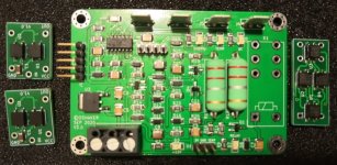
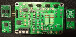
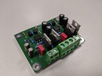
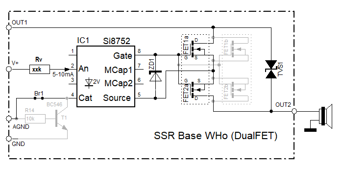
As in my case the -40V Supplyrail is not nearby/available, I'm including a 58V TVS device across D-S-S-D connection of the 60V Vdsmax MOSFETs on the SSR module (being a 20x31mm piggy-back board on the existing Amp). My SSR module features an "Enable/V+" Input to supply 5mA into the Si8752 MOSFET driver, which is derived e.g. from the +40V Amp-Rail through a DC detection circuitry and a resistor. The Si8752 AGND pin connects to another switching transistor being controlled by the (existing) "power on/off" and "AC lost" muting circuitry. So the "high active - no DC" sensor output and the high active "unmute" are effectively AND gating the Si8752/SSR activation/deactivation.
Regards,
Winfried
Thanks a lot for your patience in educating me/us!
As in my case the -40V Supplyrail is not nearby/available, I'm including a 58V TVS device across D-S-S-D connection of the 60V Vdsmax MOSFETs on the SSR module (being a 20x31mm piggy-back board on the existing Amp). My SSR module features an "Enable/V+" Input to supply 5mA into the Si8752 MOSFET driver, which is derived e.g. from the +40V Amp-Rail through a DC detection circuitry and a resistor. The Si8752 AGND pin connects to another switching transistor being controlled by the (existing) "power on/off" and "AC lost" muting circuitry. So the "high active - no DC" sensor output and the high active "unmute" are effectively AND gating the Si8752/SSR activation/deactivation.
Regards,
Winfried
@ metal, Hi! I don't have a model to predict that. But I would hazard a guesstimation that it would not be as large as the driving current at the moment of SSR cutoff, given the lossiness of the equivalent reactance of the loudspeaker system and the limited amount of kinetic energy storage within the driver unit's suspension system. We often see 1N4004 being used as clamping diode at output stage in amplifiers capable of 150W and higher, and that speaks a lot.
@wgh52, It's very kind of you. I don't see an educator in me. I myself learn from people in the forum all the time. It is my pleasure and I appreciate the opportunity to exchange information in this great place.
Your SSR module sounds like a feature rich design. I wish everything works out well for you. As far as the TVS selection goes I hope you not be annoyed by my opinion. When they spec a TVS as 58V, they often mean it will hold up against 58V, not breaking down but sort of on verge, the voltage that it really breaks down and conducts, or avalanche, is usually a few volts higher. Since your MOSFET has a 60V VDSmax, perhaps a slightly lower voltage rating TVS better suits your MOSFETs.
Your SSR module sounds like a feature rich design. I wish everything works out well for you. As far as the TVS selection goes I hope you not be annoyed by my opinion. When they spec a TVS as 58V, they often mean it will hold up against 58V, not breaking down but sort of on verge, the voltage that it really breaks down and conducts, or avalanche, is usually a few volts higher. Since your MOSFET has a 60V VDSmax, perhaps a slightly lower voltage rating TVS better suits your MOSFETs.
@nattawa
Thanks for everything, I'll use a margin of safety based on the datasheet when selecting the TVS device
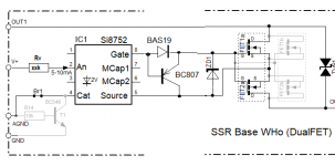
When looking at my parts depot another idea appeared to me as I do have a bunch of dual-NMOSFET devices with Rdson ~ 6mOhms & Vdsmax 90V in my drawer: What about connecting two double-FET devices in parallel per the attached schematic in order to lower the effective Rdson? This would be a handy because my PCB allows top and bottom FET mounting.
Thanks and Regards,
Winfried
Thanks for everything, I'll use a margin of safety based on the datasheet when selecting the TVS device
When looking at my parts depot another idea appeared to me as I do have a bunch of dual-NMOSFET devices with Rdson ~ 6mOhms & Vdsmax 90V in my drawer: What about connecting two double-FET devices in parallel per the attached schematic in order to lower the effective Rdson? This would be a handy because my PCB allows top and bottom FET mounting.
Thanks and Regards,
Winfried
Attachments
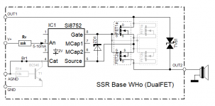
...... What about connecting two double-FET devices in parallel per the attached schematic in order to lower the effective Rdson? This would be a handy because my PCB allows top and bottom FET mounting.
Thanks and Regards,
Winfried
That will work.
As of the Si8752, I noticed in the datasheet the turn on/off time of the gate drive is specified with a gate capacitance of 100pf. In our application the gate capacitance is far greater, so the turning on/off is not even remotely that fast. Not saying that would definitely be a concern, yet if possible, better get it simulated to see if the FETs are exposed to excessive power dissipation during turn on/off with load current. The SO-8 SMD package has a lot smaller thermal mass than bigger packages, might worth a close look at the odds.
If concerned, an additional diode and a PNP transistor can help greatly shorten the turn-off, not much can be done to help the turn-on though.
Attachments
- Home
- Amplifiers
- Solid State
- Output Relays