You would have to test the circuit under all conditions. The rail time constants might effect the drop out time on that circuit, also C4 has no quick discharge path on power down.
Here is a simple delay circuit (video in post #24 of it working)
http://www.diyaudio.com/forums/solid-state/224957-simple-universal-speaker-delay-using-triac.html
The last post shows a possible option for a point to add an 'input' from a DC protection or over current circuit.
Edit... link corrected.
Mooly, I can't get back from post561 to the previous page.
I have tried F5 and no difference
Then tried Ctrl+F5 and no difference.
Using the "previous" icon takes me back 2 pages to post521 (I have 20post per page).
Clicking on the page number reproduces the same faulr, jumping back two pages.
What causes this?
It's not happened for a few months.
I have tried F5 and no difference
Then tried Ctrl+F5 and no difference.
Using the "previous" icon takes me back 2 pages to post521 (I have 20post per page).
Clicking on the page number reproduces the same faulr, jumping back two pages.
What causes this?
It's not happened for a few months.
It sounds like a corrupt temporary file Andrew. Try a browser clean up first and delete your temporary internet files.
I have come back here after consulting some other Threads. They allow normal navigation.
Why just this Thread?
Why just this Thread?
Because I think you have a corrupt file in your browser related to this thread. Un-tick 'Preserve favourites' and tick all the others to fully clean everything up.
http://www.diyaudio.com/forums/foru...act-details-certain-profiles.html#post3918620
http://www.diyaudio.com/forums/foru...act-details-certain-profiles.html#post3918620
It's working again in both IE and in Firefox. Thanks.
Did not see "preserve favourites" but the other tick to delete seems to have removed the presumed corrupted file.
Is that a cookie?
Did not see "preserve favourites" but the other tick to delete seems to have removed the presumed corrupted file.
Is that a cookie?
Last edited:
It's working again in both IE and in Firefox. Thanks.
Did not see "preserve favourites" but the other tick to delete seems to have removed the presumed corrupted file.
Is that a cookie?
Have it done auto - CCleaner - PC Optimization and Cleaning - Free Download
Run it like (below). Favorites and settings stay , cookies and the "garbage" are gone
on start-up. Same company makes "defraggler" , same automation for HDD
de-fragmentation. Error free for almost 2 years.
OS
Attachments
It's working again in both IE and in Firefox. Thanks.
Did not see "preserve favourites" but the other tick to delete seems to have removed the presumed corrupted file.
Is that a cookie?
A cookie is a small file the site in question loads onto your PC to identify you in the future. If you delete cookies then you have to re enter your login details for the site to know who you are.
You can export all your cookies to a text file which means when you do a full clean up you just import them to the cleaned browser and away you go, all logins and passwords restored with no effort.
Internet Explorer - Import and Export Cookies - Windows 7 Help Forums
Temporary files are copies of web pages you visit, the idea is that its quicker for the PC to load the page from this cache than to download it again, as long as no content on the page has changed. It really dates back to the days of dial up and slow access speeds. These days it can be more of a hindrance.
My preferred method is to set it so that just temporary files are auto deleted each time you close the browser. The middle picture in the link above shows that option (tick box) and the last picture shows the ticks against all that will be deleted each time I close IE. These days I just auto delete temporary files automatically (so just that box and nothing else ticked).
-used to do it that way. If you want to test this go to the same pageTemporary files are copies of web pages you visit, the idea is that its quicker for the PC to load the page from this cache than to download it again, as long as no content on the page has changed. It really dates back to the days of dial up and slow access speeds. These days it can be more of a hindrance.
repetitively on some of the more commercialized sites. Your cache will grow and grow.
It's not that you are getting different content , but are forced to load a different set of
ads each time. Also all the trackers will tag where you came from and try to
target your buying preferences. Only 10% of your bandwidth is content , the other 90% is ever changing dynamic targeted advertising.
PS - only the firefox/flashblock/adblock/ghostery combo can make the internet even remotely tolerable now.
OS
That's true. Lol and to think that not so very long ago a 2gb monthly allowance was sufficient. Not anymore !
Hi
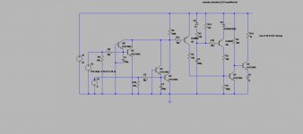
I looked at a lot of the suggestions here, I cannot find one that fit me. All I want is power up delay and DC speaker protection. Diac cannot do it easily because once turn on, it won't turn off. I finally designed my own. Attached are the .asc file, the jpeg version of the .asc file.
V1 is the rail power, say 25V or 40V. V2 and V3 is the left and right channel output from the power amp.
Then the graphs in this order:
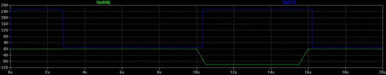
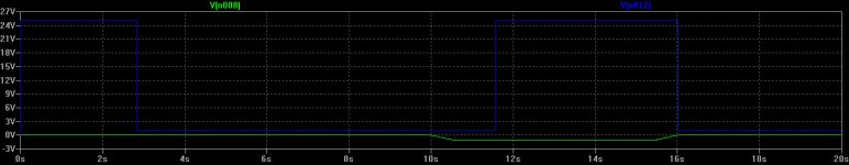
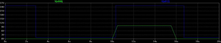
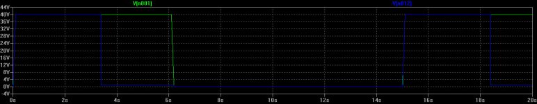
1) Power up about 3 seconds delay. Green trace is V1 that power the circuit, it power off to show the next cycle.
2) +1V DC at V2 that show the collector of Q1 goes high. Green is +1V input
3)+10V DC at V2, it's faster than -1V. Green is +10V input
4) +-1V
5)-10V
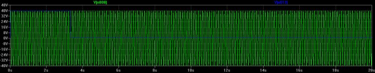
6) I set the time constant so a continuous 40Vpeak 10Hz signal will not trigger the circuit.
It looks a little cheesy, but seems to do what I want. Let me know what you guys think before I layout the pcb. Attached is the BJT file in case you want to simulate also.
Thanks
I looked at a lot of the suggestions here, I cannot find one that fit me. All I want is power up delay and DC speaker protection. Diac cannot do it easily because once turn on, it won't turn off. I finally designed my own. Attached are the .asc file, the jpeg version of the .asc file.
V1 is the rail power, say 25V or 40V. V2 and V3 is the left and right channel output from the power amp.
Then the graphs in this order:
1) Power up about 3 seconds delay. Green trace is V1 that power the circuit, it power off to show the next cycle.
2) +1V DC at V2 that show the collector of Q1 goes high. Green is +1V input
3)+10V DC at V2, it's faster than -1V. Green is +10V input
4) +-1V
5)-10V
6) I set the time constant so a continuous 40Vpeak 10Hz signal will not trigger the circuit.
It looks a little cheesy, but seems to do what I want. Let me know what you guys think before I layout the pcb. Attached is the BJT file in case you want to simulate also.
Thanks
Attachments
-
 Pulse -10V.jpg69.2 KB · Views: 122
 -
 Pulse -1V.jpg67.3 KB · Views: 349
 -
 Pulse +10V.jpg67.9 KB · Views: 358
 -
 Pulse +1V.jpg66.3 KB · Views: 410
 -
 Power up delay.jpg71.6 KB · Views: 460
 -
 Speaker protection rev2a.jpg86.7 KB · Views: 462
 -
Speaker protection rev2a.asc4.6 KB · Views: 115
-
 10Hz 40V input.jpg229.3 KB · Views: 166
 -
standard_BJT modified.txt56.9 KB · Views: 110
Last edited:
It all looks fairly standard stuff, perhaps just knock it up as a breadboarded test first and make sure it all works as expected. C1 and C2 are different ?
It all looks fairly standard stuff, perhaps just knock it up as a breadboarded test first and make sure it all works as expected. C1 and C2 are different ?
I started out with 100uF for both, but I work on only V2 side. They are supposed to be the same.
I am debating whether I should use a dual opamp to do a 2 pole butterworth or even steeper roll off filter at the input. That way, I can roll off the higher frequency faster so I can lower the value of C1 and C2. That will shorten the time for the circuit to trip when a fault condition happens. Right now, when the DC is 1V, it takes over a second for the relay to open up. But I guess it's ok as lower DC would not burn the speaker. It's just a lot of hazzle to put in any IC as they want lower voltages.
I am half way laying out the pcb, might as well sent it out. This is an easy circuit, simulation looks good, no point of breadboarding it.
I too found that low offset gives a slow trigger response and a high offset gives a faster response.
Typical values for my circuit values were
+2Voffset, 1 to 2 seconds delay till trigger.
-2Voffset 0.6 to 1.5seconds delay till trigger.
+20Voffset 40ms delay till trigger.
-20Voffset, 35ms delay till trigger.
The -ve offset was always a little faster than the +ve offset.
This applied in both the simulation and on the breadboard circuit. The relay then adds on it's own "delay" till it opens.
Now the problem.
In the simulation I found that at some low frequency around 5Hz to 15Hz, depending on the RC values I was using, that the trigger was not a clean OFF, it started to oscillate and would not activate the relay. The frequency band was usually quite narrow.
On the breadboard, I could replicate this not trigger operation. eg it might not trigger at 11Hz 40Vpk (28Vac sinewave) and clearly trigger at 6Hz 40Vpk. But over a very narrow range around 8Hz to 10.5Hz, it would oscillate and not trigger.
BTW, I try to avoid using an electrolytic in the filter/timer. Due to increasing leakage current while lying for months/years as an uncharged/inactive capacitor.
1uF to 3u3F MKT Mylar etc are cheap and small enough and very reliable if you choose a suitable R value.
Last edited:
BTW, I try to avoid using an electrolytic in the filter/timer. Due to increasing leakage current while lying for months/years as an uncharged/inactive capacitor.
1uF to 3u3F MKT Mylar etc are cheap and small enough and very reliable if you choose a suitable R value.
Thanks for your reply. I am hoping leakage is not an issue with electrolytic caps. C1 and C2 always sit at ground level, leakage is not going to be a problem. C3 gets charged and discharged every power cycle, so it's active. Also, the pull up of C3 is with a 51K, it's not that low that leakage can cause trouble.
I checked Digikey. I can only get ceramic to 100uF 6.3V. I am not comfortable to raise R7 and R8 to above 20K. The problem with this design is Q4 and Q8. These two are detecting the output going negative. there is no current gain at these two transistors as it's operating in common base. Increasing the value of R7 and R8 to lower the value of C1 and C2 will decrease the current to the point it's not going to trigger the circuit.
I was thinking about putting a dual opamp to create a 2 pole butterworth low pass filter at the input to decrease or eliminate the capacitance of C1 and C2. Also opamp can drive current. But it's a lot of complications as the opamp can't take the rail voltage. This window comparator is not easy to implement if you cannot use opamps or comparators. I need to have a way to get current gain of Q4 and 8 before I can increase resistance to lower C1 and C2 to the point I can use ceramic non polar caps.
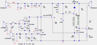
This is my schematic that I almost finish the pcb. I add 3.3ohm resistor from the connector ground of each power amp to the board ground to break the ground loop. I change the original 220uF cap to ceramic caps. I use two 100uF 6.3V ceramic cap in parallel. I cannot change the 100uF 100V turn on delay cap, no ceramic cap that can take 100V at that value.
Attachments
Hi
I looked at a lot of the suggestions here, I cannot find one that fit me. All I want is power up delay and DC speaker protection. Diac cannot do it easily because once turn on, it won't turn off. I finally designed my own. Attached are the .asc file, the jpeg version of the .asc file.
V1 is the rail power, say 25V or 40V. V2 and V3 is the left and right channel output from the power amp.
Then the graphs in this order:
1) Power up about 3 seconds delay. Green trace is V1 that power the circuit, it power off to show the next cycle.
2) +1V DC at V2 that show the collector of Q1 goes high. Green is +1V input
3)+10V DC at V2, it's faster than -1V. Green is +10V input
4) +-1V
5)-10V
6) I set the time constant so a continuous 40Vpeak 10Hz signal will not trigger the circuit.
It looks a little cheesy, but seems to do what I want. Let me know what you guys think before I layout the pcb. Attached is the BJT file in case you want to simulate also.
Thanks
Here is a new fresh suggestion (below DC detect).
Q2/3 reference off the amp's rails , The zener keeps Q4/5 safe , and Q5's collector
pulls down (whatever) - a IC's input , or relay driver.
As far as how well this "snippet" of the whole circuit works ? The two times
I triggered it in 6 months , the protection MOSFETS switched off the speakers
before the DC even made the woofer move a few millimeters.
OS
Attachments
ThanksHere is a new fresh suggestion (below DC detect).
Q2/3 reference off the amp's rails , The zener keeps Q4/5 safe , and Q5's collector
pulls down (whatever) - a IC's input , or relay driver.
As far as how well this "snippet" of the whole circuit works ? The two times
I triggered it in 6 months , the protection MOSFETS switched off the speakers
before the DC even made the woofer move a few millimeters.
OS
Let me verify:
1) I assume J4 is the rail with pin 1=-V, pin3=+V. They feed Q2 and Q3 resp.
2) Data bus D7 is something else that control Q6 to turn off relay K1 and K2.
3) J2 and J3 are from output of the amp to speaker. Both drive through the low pass of R=47K and don't know how to read the C. What is 10^7? pF? If so, you only have 5uF and the low pass is 1/[6.28 X 47,000 X 5uF]=0.68Hz.
4) In order to turn Q2 and Q3 on, you have to have one side of the speaker larger than 4Vbe=2.8V before Q2 and Q3 turn on and open Q7 to open the relays.
If this is correct, you need 2.8V of fault to the speaker to trip the relay. In my design, I trip at over 0.7V. My simulation show tripping at 1V DC, much more sensitive.
Also, I think your low pass cut off at 0.7Hz is not enough, that mean at 7Hz, the attenuation is only divided by 14. I am using 10K and 200uF that gives me cut off at about 0.07Hz in order not to trigger the relay when I put in a 40Vpeak 10Hz signal. And this is only good for +/-40V rail. It might fail at higher voltage.
Last edited:
- Home
- Amplifiers
- Solid State
- Output Relays