I feel even better of my design after looking at this. The frontend Q5 and Q6 is exactly the same as mine. Mine is better. That circuit use Q3 as emitter follower which has no voltage gain. Q3 drive directly to Q4 which is the relay driver already. The problem is worst on the -ve failure that Q5 is common base like mine. No gain from Q3 and drive Q4. This only has a single stage voltage gain of Q4. there is a big uncertainty window where the output can wander around. this is not even a good circuit. The circuit is very slow if the fault is only 1V DC. You need a lot of gain to speed it up once it crosses the threshold of 0.7V.I'd suggest that you consider the circuit used in the "Speaker Turn On Delay and DC Protector Board Set (V3)". Even if you don't want to use the PCB, you could still benefit from the fact that by now the circuit should have been thoroughly debugged.
http://www.diyaudio.com/forums/diya...ker-turn-delay-dc-protector-board-set-v3.html
The circuit is shown in post #5 of that thread, and C3 in that circuit performs the same function as my C4.
Personally, I would also replace the mechanical relay in that circuit, with a solid state relay - which is, after all, the subject of this thread.
So far, yours the only one that I consider good. Just because someone actually selling does not mean it's good. You have to analyze the circuit, not just because others are selling it. This is DIY, the fun is designing it. Understanding it and take the best.
Your C4 is not the same as C3 in this circuit. C3 is for power up delay. C3 charge up slowly and it's not until the output of Q3 goes above the zener voltage of D2 that it turn on Q4 to power the relay. It is not for de-spike that junction.
I just got the quote back of my circuit. $20 for 10pcs!!!
Last edited:
Why not try to protect everything at the same time?
I cannot make the speaker, I can make the amp. More importantly, when something goes wrong with the amp that trigger the failure, you have to open it up. changing 2 transistor or changing 6 transistor does not make much of a difference.
I intentionally not putting any current limiting protection in the OPS, less is more and I don't want to contaminate the circuit. I want perfect layout for the best signal performance. all these protection are on a separate board away from the signal path.
Output relays can short. Output devices can stink up your house when they fail. That smell can hang around for weeks.
I'm not a fan of current limiting protection either but an massive overcurrent/ overtemp shutdown doesn't hurt. A redundant system to shut the amp off on fault detection isn't a terrible idea and won't harm sound quality.
I'm not a fan of current limiting protection either but an massive overcurrent/ overtemp shutdown doesn't hurt. A redundant system to shut the amp off on fault detection isn't a terrible idea and won't harm sound quality.
Ha ha, that's true about the smell. But those are taken care of by rail fuse, doesn't it?Output relays can short. Output devices can stink up your house when they fail. That smell can hang around for weeks.
I'm not a fan of current limiting protection either but an massive overcurrent/ overtemp shutdown doesn't hurt. A redundant system to shut the amp off on fault detection isn't a terrible idea and won't harm sound quality.
I use SS relay and it's already designed on the OPS. I use 4 of the MOSFET with 4.5mohm on resistance. It's like two SS relay in parallel.
I have to think if there's an easy way to shut the amp off.
Your C4 is not the same as C3 in this circuit. C3 is for power up delay. C3 charge up slowly and it's not until the output of Q3 goes above the zener voltage of D2 that it turn on Q4 to power the relay. It is not for de-spike that junction.
I don't disagree that C3 in that circuit provides power-up delay, but think it will also have the effect of eliminating spikes which may be generated by the detector, when it's near its switching point.
I just got the quote back of my circuit. $20 for 10pcs!!!
I'm looking forward to the photos already 🙂
Ha ha, that's true about the smell. But those are taken care of by rail fuse, doesn't it?
I use SS relay and it's already designed on the OPS. I use 4 of the MOSFET with 4.5mohm on resistance. It's like two SS relay in parallel.
I have to think if there's an easy way to shut the amp off.
Everyone cringes when I mention this but a microcontroller is a nice easy option. It makes timing adjustments for softstart and speaker on delay a breeze too.
Everyone cringes when I mention this but a microcontroller is a nice easy option. It makes timing adjustments for softstart and speaker on delay a breeze too.
Ha ha, did too many of them in my career, I kind of want to stay away and go old school as these kind of circuit too simple to invest time into the learning curve of MPU. I might do it after I design and build a tube power amp. But for now, I just want the amp.
I don't disagree that C3 in that circuit provides power-up delay, but think it will also have the effect of eliminating spikes which may be generated by the detector, when it's near its switching point.
I'm looking forward to the photos already 🙂
You had good designs in the last two posts. At the risk of being inappropriate as I don't know you whether you are an engineer or a hobbyist only. If you designed the two circuit you posted, you have a neck of designing and fast adapt to changes. I almost go with your second design until the -ve supply. It is easy to work with it by using the -ve supply to do the power up delay and that will cover the problem.
I went with my design as it's so close and I finish layout the board while this post is still going. More like laziness to do extra work to change than insisting on my own design.
Again, I might be inappropriate, if you are young and only a hobbyist, this might be your calling. If you are an engineer....Sorry, my bad.
Attached is the plot of the two layers
Attachments
Last edited:
You had good designs in the last two posts. At the risk of being inappropriate as I don't know you whether you are an engineer or a hobbyist only. If you designed the two circuit you posted, you have a neck of designing and fast adapt to changes. I almost go with your second design until the -ve supply. It is easy to work with it by using the -ve supply to do the power up delay and that will cover the problem.
Thanks, it's over 30 years since I changed career from H/W design to S/W, so these days it's just a hobby. I came up with the 4-transistor detector when I was considering bridging a pair of Class-D amps to drive my vintage Fane Crescendos. I hadn't seen any other detector designs for bridged amp configuration, but I doubt the design is original. It was trivial to adapt it for single-sided (non-bridged) use.
I went with my design as it's so close and I finish layout the board while this post is still going. More like laziness to do extra work to change than insisting on my own design.
It's the best way to learn.
Before you order the PCBs, I suggest you check that your circuit prevents the detector pulses from reaching the relay. I was able to make this happen in your circuit in post #572 by using the following settings for the input voltage generator (V2): DC offset=0.45V, Amplitude=20V, Frequency=10Hz. The frequency was your original value, but I reduced the signal amplitude, and introduced the DC offset.
Before you order the PCBs, I suggest you check that your circuit prevents the detector pulses from reaching the relay. I was able to make this happen in your circuit in post #572 by using the following settings for the input voltage generator (V2): DC offset=0.45V, Amplitude=20V, Frequency=10Hz. The frequency was your original value, but I reduced the signal amplitude, and introduced the DC offset.
The trigger is the sum of DC offset + the amplitude of the signal after the low pass filter. You put 0.45V DC, you eat up a lot of the margin. I am not surprised. If you have 0.45V at the output, you got a problem!!!
There is no magic on this, it's just RC, the higher the RC, the less it's susceptible to the signal false trigger. BUT the slower it takes to trigger in a fault condition. If you do the test on others, it's the same, it's just what do you consider to be acceptable.
Then if you use your first circuit that trigger at 1.4V, you will not see this problem. But then the trigger is 1.4V. So it is a compromise.
I use 10K to increase the current at the input, but if it ever fail, I'll change to 20K. Simulation show good result at 20K, I use 10K to provide a little more kick.
My career path is like opposite from you. I started out doing a lot of firmware, I slowly change to designing hardware and to pure analog and RF. Designed a lot of microcontrollers in the 80s and 90s but more and more to pure analog and RF. I don't like digital anymore, that's the reason I rule out MPU controller for this.
Last edited:
This illustrates the purpose of my C4 - it prevents the pulses from reaching the output.
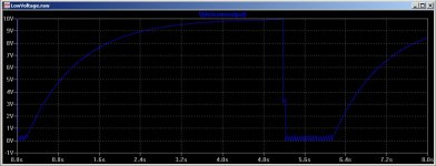
In the attached sim of my circuit, I have adjusted the input voltage to be in the critical region where the detector generates pulses. You can see the pulses from the detector on "TP1", they have the same frequency as the sine wave in the input signal (20Hz). However the circuit around C4 prevents the 20Hz pulses from reaching the "DetectorOutput".
In the sim, the DC error is applied at 5 seconds, and removed 1 second later.
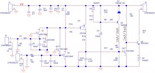
The attached images are: 1) the schematic, 2) the pulses on "TP1", 3) the signal at "DetectorOutput" where the pulses have been suppressed by C4. I'm also attaching the .asc and the referenced file containing Bob Cordell's models (this is available from his website).
In the attached sim of my circuit, I have adjusted the input voltage to be in the critical region where the detector generates pulses. You can see the pulses from the detector on "TP1", they have the same frequency as the sine wave in the input signal (20Hz). However the circuit around C4 prevents the 20Hz pulses from reaching the "DetectorOutput".
In the sim, the DC error is applied at 5 seconds, and removed 1 second later.
The attached images are: 1) the schematic, 2) the pulses on "TP1", 3) the signal at "DetectorOutput" where the pulses have been suppressed by C4. I'm also attaching the .asc and the referenced file containing Bob Cordell's models (this is available from his website).
Attachments

I see what you are trying to show. I gave it a lot of thoughts. Basically, what you want is once it triggered, C4 will slow down the recovery. the 20V sine wave will to toggle the output back and fore.
I even changed my circuit to have that so once the circuit pull low, it will have a dead time before it can recover, so any frequency driving will be less likely to create oscillation like at the output.
BUT, this is a man made assumption. In real world, there won't be an offset of 0.6V if the amp is working. If you have fault condition that it has 0.6V DC, nothing will burn if the output is chopping off like this.
So it sounds funny, so what. More noticeable for you to stop and fix it!! It won't hurt the speaker. It might be even a good thing!!! So you know right away and take care of it before more things get burned.
Remember, this is a speaker protection, protecting the speaker from burning. People can come up with all different scenarios and make the circuit much more complicated. But the bottom line is whether it can protect the speaker.
I likely put in this feature for the hell of it. But I really don't think it's necessary. Attached is the .asc files, you can use the model I posted before, or just any Cordell's library. They are all there.
Attachments
Last edited:
I likely put in this feature for the hell of it. But I really don't think it's necessary. Attached is the .asc files, you can use the model I posted before, or just any Cordell's library. They are all there.
Thank you for taking time to understand what I was talking about.
If you're using a solid state relay, then I agree the feature is not necessary, but if the relay is mechanical, and the relay chatters when the circuit is on the verge of triggering, this might increase the risk of the contacts welding together - as they could be carrying a high current at the time.
Don't add the feature unless you want it - my only motive was that you should understand the issue - and clearly you do.
Thanks for posting the .asc file, it all looks good to me - I can't see any problems.
Thanks for your time too. I am putting it in even though it increase the pcb size a little and might cost a little more. Yes, I already designed the SS relay into the OPS board( I separated OPS from IPS/VAS for convenience of changing configuration), I never thought about the mechanical relay contact at all, I never consider chattering issue. That makes the whole world of sense to have that for mechanical relay.
Even though it's not necessary, but your concern have a valid point, so, in it is!!! Since I posted the .asc, I looked for the PNP for that as the KSA992 cannot handle the large current of discharging the cap. I decided to use the ZTX704 PNP darlington404 | DigiKey, I since added another KSA992 into the simulation. It is even slightly better.
Attached is the .asc file with the original and the darlington modification. If you play around with the two signal generators like what you did, you'll find the darlington work slightly better with less chatter at the lower fault signal end. Also attached is my final schematic of my pcb.
Thanks
Attachments
Even though it's not necessary, but your concern have a valid point, so, in it is!!! Since I posted the .asc, I looked for the PNP for that as the KSA992 cannot handle the large current of discharging the cap. I decided to use the ZTX704 PNP darlington404 | DigiKey, I since added another KSA992 into the simulation. It is even slightly better.
Yes, I hadn't noticed, it's too much current for the KSA992. An alternative to using the darlington, would be to tweak the resistor values. Increasing R31 to 1K would reduce the current to about 40mA and be within KSA992's ability. Also increasing R20 to 47K, would increase the discharge time-constant, and ensure that (with a 10Hz input), C8 still has 20-25V on it when the next pulse comes along - thus ensuring Q10 is always held on between the pulses. But there's lots of way to do it, and it really comes down to personal preference.
I have read this whole thread, quite interesting. I may look at using SSR. Has anyone here used mosfets to switch power rails off, on fault conditions?
MI
MI
I have read this whole thread, quite interesting. I may look at using SSR. Has anyone here used mosfets to switch power rails off, on fault conditions?
MI
Member Jwilhelm has a whole SS protected PS with DMOS already prototyped.
OS
Hi,
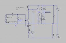
This is for MadInventor. I have a design that protect the speakers by controlling the rails voltage and if there it is a high current output fault then the rails voltage will be shutdown immediately. Also the rails voltage are controlling by the micro. Attached it is a drawing showing how it is done.
This is for MadInventor. I have a design that protect the speakers by controlling the rails voltage and if there it is a high current output fault then the rails voltage will be shutdown immediately. Also the rails voltage are controlling by the micro. Attached it is a drawing showing how it is done.
Attachments
I was curious, why the big PA amplifiers are using automotive relays, which looks a really bad solution in case of DC failure.
I just checked the price of the high voltage (>300V) and low Rds (<20mohm) MOSFETs, and now understand the reason.
The absolutely best solution I've ever seen is in the Mackie M1400, where crowbars are shorts the rails to the GND, and kills the rail fuses.
Sajti
I just checked the price of the high voltage (>300V) and low Rds (<20mohm) MOSFETs, and now understand the reason.
The absolutely best solution I've ever seen is in the Mackie M1400, where crowbars are shorts the rails to the GND, and kills the rail fuses.
Sajti
Thanks, everyone for your input, I found another thread on this subject, http://www.diyaudio.com/forums/solid-state/155939-mosfet-relays-10.html will need to assimilate, I found some of the photocouplers talked about. Will need to do some experiments. The rail shut-down, I will probably use on my BJT amp project, have a bunch of MJ15003/4 to use(bought long ago for a leach project, I think?), any suggestions? Not sure I want to incorporate a MCU into any project amps right now, I still need to write code for my mosfet preamp nano.
@tauro0221 do you have the mosfet gate switching and power dissipation, worked out. I have given some thought to using a MCU in amp designs , but interfacing various info bias, fault detection, temp, etc. is more time, then I probably want to spend, right now.
MI
Hey, I noticed I can edit this post, I must be off "double secret probation", ....sorry couldn't help it.
Last edited:
- Home
- Amplifiers
- Solid State
- Output Relays