Has everyone discovered the .wav in and .wav out feature of of LTspice?
We can listen to our simulations in 16bit 44.1k.
You can also use the output of your preamp and use it as input to your poweramp to see the distortion of the combo.
Or you save the ripple on a psu sim and use it as ripple on the psu of your preamp. The sky is the limit.
BTW Frans your .param is interesting. Hadn't realized something like that was possible.
Jan
P.s. This is about the best possible (post #8458), changing Q3 and Q4 to an Darlington or a CFP pair makes a small improvement and should [in reality] be considered for implementation.
In reality it may be that using a Darlington or CFP input configuration eases the need for 'total'-equality and it will lower the input current to 20...30nA (compared to almost 2mA in this simulation).
The canceling effect of the two totally equal transistors should be further investigated by tinkering the transistor parameters (making them different) or by using unequal (different parts numbers) transistors.
Last edited:
...BTW Frans your .param is interesting. Hadn't realized something like that was possible.
Now if only someone found my work interesting
")
Has everyone discovered the .wav in and .wav out feature of of LTspice?
We can listen to our simulations in 16bit 44.1k.
Where have you been
(the files were taken down some time ago I'm afraid)
Welcome to the (virtual) listening room.
It is one of the reason some prefer CFAs.I think Jan has right, one more
If you reduce the feedback path impedance, in order to optimise the bandwidth of a VFA, you are loosing the advantage of the "symmetry" in regard to cancelling the distortion of the input stage. If you reduce both, in order to keep them equal, the signal input impedance will be too low in regard to the 10K standard.
Where have you been
(the files were taken down some time ago I'm afraid)
Welcome to the (virtual) listening room.
Well I was busy building real test equipment like oscillators and such.
And to think I could have done it all in spice.
Are we getting a bit twisted in our old age?
So we still haven't unraveled the root cause of the non-linear Iin?
Jan
Hi Jan,
I believe that is correct, at least as near as I can tell.
The hypothesis of Doug that it is the nonlinearity in the input current that is required to produce the nonlinear signals in the forward path required to oppose those that would occur at the output in the absence of NFB is one that I have been looking at closely in simulation by looking at the distortion at each major node or path in the amplifier working backwards from the output. Stay tuned. As expected, the signals at those points are distorted, but it is not yet clear that that amount of distortion is accounting for the observation regarding input current nonlinearity.
I have also been looking at distortion in the input current that is in the common mode, caused by Early effect distortion in the IPS tail current source. The tail current source in Doug's Blameless design being discussed here has quite poor Early effect immunity and not great output impedance due to it being biased from the VAS feedback current source. We must always bear in mind that it is very important to have a near-ideal tail current source in order to achieve lowest distortion. The use of a very well-balanced current mirror as the IPS load helps a lot in this regard, but does not help in regard to nonlinearities and power rail garbage injected into the input current.
Cheers,
Bob
It is one of the reason some prefer CFAs.
If you reduce the feedback path impedance, in order to optimise the bandwidth of a VFA, you are loosing the advantage of the "symmetry" in regard to cancelling the distortion of the input stage. If you reduce both, in order to keep them equal, the signal input impedance will be too low in regard to the 10K standard.
Yes, and is also a indication that increasing the input impedance (using Darlington's or CFP's) will lower distortion.
But the one distortion you can never solve is the inequality [in real life] of the input transistors, matching transistors will not solve all.
Maybe there is a good case here for using an input-opamp, while, some of these opamp's will have extremely low input distortions (as low as -180dB in closed loop).
Are we getting a bit twisted in our old age?
Not really
If you read the thread you will see those that took part really enjoyed it.And don't forget it was you that seemed thrilled at the idea only a few posts back
You should try it.We did a simulation of the old Texan as well, somewhere buried in this lot:
Test your ears in my new ABX test
Hi Bob,
I wasn't taking a shot at you or the practice of simulation. It was more an observation that some people take the simulation as gospel without acknowledging that a simulation is an approximation of the truth. All those decimal points it displays doesn't help the situation at all either.
For the record, I own and have read books from both you (Bob) and from Douglas. I find all of them are valuable references, even when the two of you disagree. I find that I greatly prefer J-Fet inputs over BJT's. I think that distortion of the input signal before it enters an amplifier is a real effect that is reduced when a low impedance output preamplifier is used in the combination. This is just an unmeasured impression that some of my friends also accept as "a thing". Certainly an input buffer can mitigate most of this issue. The first major consumer amplifier I know of that uses an input buffer would be the Marantz 500 and others in the line. More recently, Nakamichi resurrected the input buffer calling it "HTA". I forget what that stands for, but their listening panel found value in it enough so that they included it in receivers and gave the effect a marketing name. I'm pretty sure that there are many examples of this in the market. It does warrant further investigation, that's for sure. I'm going to bet that a J-Fet diff pair has more advantages than just lower audio rectification of RF signals. The only BJT input that comes close to this are the complementary differential pairs that John Curl popularized. Only when that design is executed properly though.
So, simulate away, but never forget that a physical circuit is required to be tested before you can draw any solid conclusions. Simulation is a valuable tool. I wish I knew how to use these programs, so I design on paper instead.
Best, Chris
Hi Bob,
I wasn't taking a shot at you or the practice of simulation. It was more an observation that some people take the simulation as gospel without acknowledging that a simulation is an approximation of the truth. All those decimal points it displays doesn't help the situation at all either.
For the record, I own and have read books from both you (Bob) and from Douglas. I find all of them are valuable references, even when the two of you disagree. I find that I greatly prefer J-Fet inputs over BJT's. I think that distortion of the input signal before it enters an amplifier is a real effect that is reduced when a low impedance output preamplifier is used in the combination. This is just an unmeasured impression that some of my friends also accept as "a thing". Certainly an input buffer can mitigate most of this issue. The first major consumer amplifier I know of that uses an input buffer would be the Marantz 500 and others in the line. More recently, Nakamichi resurrected the input buffer calling it "HTA". I forget what that stands for, but their listening panel found value in it enough so that they included it in receivers and gave the effect a marketing name. I'm pretty sure that there are many examples of this in the market. It does warrant further investigation, that's for sure. I'm going to bet that a J-Fet diff pair has more advantages than just lower audio rectification of RF signals. The only BJT input that comes close to this are the complementary differential pairs that John Curl popularized. Only when that design is executed properly though.
So, simulate away, but never forget that a physical circuit is required to be tested before you can draw any solid conclusions. Simulation is a valuable tool. I wish I knew how to use these programs, so I design on paper instead.
Best, Chris
BTW, speaking of input buffers, the use of emitter followers in front of the input LTP was a distinguishing feature of Tom Holman's APT-1 amplifier. It was cheap and simple, and added very little to the noise. It greatly reduced input bias current and input signal current (and thus the amplitude of any nonlinear input currents).
Cheers,
Bob
Cheers, Mr. Didden!It's a bit like masturbating. If you do it often enough you start to think it's the real thing ;-)
... the use of emitter followers in front of the input LTP was a distinguishing feature of Tom Holman's APT-1 amplifier. It was cheap and simple, and added very little to the noise. It greatly reduced input bias current and input signal current (and thus the amplitude of any nonlinear input currents).
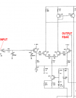
Here it is. I wonder whether R6 and R13 add very little to the noise.
_
Attachments
Not really
And don't forget it was you that seemed thrilled at the idea only a few posts back
We did a simulation of the old Texan as well, somewhere buried in this lot:
Test your ears in my new ABX test
I was joking in response to Jan's comment.
Cheers, Mr. Didden!
Prosit! Happy New Year!
Hi Bob,
i "think" i also read he would have preferred to use a dual JFET as the input LTP if he could have found one at the the time that met his constraints, one of which was he wanted a US part.
mlloyd1
i "think" i also read he would have preferred to use a dual JFET as the input LTP if he could have found one at the the time that met his constraints, one of which was he wanted a US part.
mlloyd1
BTW, speaking of input buffers, the use of emitter followers in front of the input LTP was a distinguishing feature of Tom Holman's APT-1 amplifier. It was cheap and simple, and added very little to the noise. It greatly reduced input bias current and input signal current (and thus the amplitude of any nonlinear input currents).
Cheers,
Bob
Hi Bob,
i "think" i also read he would have preferred to use a dual JFET as the input LTP if he could have found one at the the time that met his constraints, one of which was he wanted a US part.
mlloyd1
Probably so. I used the National NPD5564 in my MOSFET power amp with error correction circa 1983. I don't recall how expensive it was at the time. I'm guessing it was available when Tom was doing the his design, but cost and availability might have been issues. The NPD5564 was a wonderful low-noise part, with good transconductance and available offset of less than 10mV. In terms of characteristics, I think it was much like the Toshiba '389 and the LSK389. Not sure if the Toshiba part was out before or after the 5564. These days I like the LSK489 for power amp front ends.
Cheers,
Bob
I wonder if "Distortion in low-noise amplifiers" by Eric F. Taylor, Wireless World August, 1977
might shed any light on the input current distortion question. We've discussed the article back in
2005 but I've not looked at the article since then. I remember that someone had it in .pdf format.
Found it in .pdf format, in case there is interest: http://www.keith-snook.info/wireles...d-1977/Distortion in low-noise amplifiers.pdf
Last edited:
We can calculate the nonlinear base current due to Vaf to see if it matches the distortion figures.
Cordell's BC550C model tells me Vaf is 162 and from experience Hfe is about 500. Let's say 20Vce, 5mA Ic, and 1V input.
Vaf is the voltage at which Hfe doubles (Ever heard that before? I hadn't, until I figured it out). So from 0 to 20Vce Hfe rises by 500Hfe/162Vaf*20Vce=+61.7Hfe at quiescent. 561.7Hfe/162Vaf*1Vppce=3.47Hfepp variation across a 1V input sine wave. 5mA/561.7-5mA/565.17=54.7nApp total error base current, which we can assume is mostly 2nd harmonic.
The Vbe modulation due to this current is canceled by the symmetry of the LTP so we can set it aside.
So let's assume 1k total unbalanced source impedance. 57nA*1k means 57uV error per 1k imbalance. 57uV error in 1V is 0.0057%. Most of this is still the fundamental though so it doesn't contribute to THD.
I've compared simulated Vaf directly with Vaf measurements and the real Vaf is nonlinear whereas the simulated Vaf is not. I would say that outside quasi-saturation, Vaf is probably better than 5% linear within a 1Vce range. This would make our final THD figure somewhere under .0057%*5%=.000285% (the data is noisy so it could be much lower).
Note that even if all of the Early effect error were harmonics, THD could not be more than 0.0057% with 1k unbalanced source resistance. For instance if you said that Early effect could cause 0.005% distortion (I don't have Self's book so I don't know what he claimed), then you are saying that the base current is 88% harmonics.
But if that were due to Early effect over a 1V change in Vce, then over 20V or so those errors would compound and this would easily be visible on Ic/Vce charts in the datasheet. In reality those lines are usually ruler-flat outside of quasi-saturation. So in a way the datasheet actually disproves that a large amount of harmonics are coming from Early effect.
So while simulation might not catch all the nonlinearities of Early effect, the discrepancy is not necessarily very significant unless you are at very very low distortion.
Note that this in no way addresses distortion coming from Cob nonlinearity.
Last edited:
- Home
- Amplifiers
- Solid State
- Bob Cordell's Power amplifier book