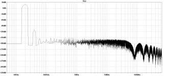
For the Power level and freq and Z it is excellent.... but at 200W or less (the design/spec output), it is well under .001%. .0002-0005% 1W-200W into 2 Ohms.
View attachment 654032
Much better at higher load Z -----> 🙂 eg 8 Ohms.
View attachment 654033
Measured..... not SIM
CFA -- 400+ v/usec; very low noise.
THx-RNMarsh
Mr. Marsh,
when reviewers measuring @ 1khz or at higher frequency, they usualy cut the scale below 1khz. I think that part is important to consider.
What hapens with LF noise floor, when amplifier is both channel highly loaded?
Is it LF power supply harmonics and noise at same small level, like 20kHz THD+N?
At quiscent condition, or at low power, usualy there is not much stray fields from transformer, but at higher level they poluting around...
The potential gain from further analysis is to discover you can eliminate the input buffer by making a simpler change to the amplifier, therefore reducing cost in several ways.
As an author you are not obliged to exhaustively tackle every possible tool in the designer's arsenal. That would be impossible. This is why we have such a thing as philosophy. If you know the philosophy of low distortion design then you don't need to have everything explained to you, you can figure out the details as you go along.
In so far as a book provides facts to the reader it is an empirical work, and in so much as it explains how discover facts for yourself it is philosophical. In principal, the empirical shortcomings of a book should be made up for in the philosophy which in it's ideal form will allow the reader to re-create the knowledge in the book as well as whatever further knowledge he needs.
It is my observation that most books on audio design are strong on empirical knowledge, but weak on philosophy. The result is that the inevitable empirical blind spots are hard for even very conscientious readers to fill in.
VERY nice post Kean. Thanks.
Jan
The potential gain from further analysis is to discover you can eliminate the input buffer by making a simpler change to the amplifier, therefore reducing cost in several ways.
But can you? Most practical amplifiers are going to have a buffer/amplifier to present a high input impedance, or a balanced input amplifier, or a bandwidth definition filter.
A standard Blameless amplifier has a relatively low input impedance if the input bias resistor is made the same as the feedback resistor to minimise offset voltages; this can be avoided if you use a DC servo but that puts the cost up again as you will need a FET-input opamp with good DC accuracy.
Having said that I would not want in any way to discourage anyone who is keen to do the analysis. Go to it!
Hi Doug,
That pretty much says it all. I see arguments over a simulated circuit all the time. It's similar to a digital meter when people believe that each digit is significant. That's how technology can lie to you.
-Chris
"As I'm sure you will agree, SPICE is sometimes a handy tool but measurements are the reality."
This is certainly true for a given amplifier measured in a given way. However, we learn by trying to understand discrepancies between two approaches, here between measurement and SPICE. SPICE is a very capable tool, but we all understand that its results cannot be always expected to be the same as those in the real world, whether that limitation is by circuit implementation realities, measurement realities, or SPICE modeling realities. Nevertheless, when SPICE results differ so significantly from reality as in the rather simple case at hand (at least my SPICE results), it should raise a very big red flag. I really don't care one way or the other whether the phenomena exists to the extent asserted by Doug based on his measurements. And I'm perfectly happy to have egg on my face if I screwed up in the SPICE simulation.
What I care about is understanding the true source of the phenomena and the true source of the discrepancy between Doug's measurement results and the SPICE results. I for one do not at this point know the answers to those 2 questions for this example, and I am not afraid to admit it. We will not learn anything by just waiving our hands and saying that SPICE doesn't model things well, especially in a simple situation as this one. Even if this phenomena truly exists in Doug's amplifier, it is important to understand why, so that we will know whether the phenomena can be generalized to other designs and how to mitigate it.
Doug has basically put his stake in the ground by saying that if the feedback has reduced the nonlinearity of the amplifier in closed loop, then there must be nonlinear signals existing in the forward path of the amplifier to correct those nonlinearities that would otherwise appear in the output. Then, if that is so, he argues that there must be nonlinearity in the input current of the amplifier, and that nonlinear current will cause a nonlinear voltage to appear across the source resistance (as distortion that is input to the amplifier). This is all absolutely correct.
But we do not know that this nonlinear input current is the dominant cause of the phenomena. We don't know if this hypothesized cause is big enough. If it is, then SPICE is somehow missing a very important and rather straightforward source of distortion. This, to me, is the head-scratcher.
If SPICE is THIS BAD at predicting a distortion phenomena, I really want to know. And I really want to know why.
Cheers,
Bob
Edmond's experiment
In the model BC547C-x on the schematic below, which is a copy of the LTSpice BC547C, I have set CJC and CJE to zero. From the .op command, one gets in the Spice log Cbc=0; Cbe remains larger.
The spectrum for unbalanced impedances is then almost as good as the balanced one from post #8434.
Using additionally BC557C-x in the current mirror changes almost nothing.
Matthias
The experiment from post #8434 is the right opportunity to repeat that in a slightly different setting.Hi Pete,
Please have a look at Super TIS fig. 5 and the text just above fig. 6. If I alter the value of R1, thus introducing an unbalance, the distortion does increase (at least according my simulation). But this does not happen if I zeroed all the capacitances of the input transistors. So I concluded that the distortion increase is due to the (nonlinear) Miller effect.
Not sure if this applies to other input configurations, of course.
Cheers, E.
In the model BC547C-x on the schematic below, which is a copy of the LTSpice BC547C, I have set CJC and CJE to zero. From the .op command, one gets in the Spice log Cbc=0; Cbe remains larger.
The spectrum for unbalanced impedances is then almost as good as the balanced one from post #8434.
Using additionally BC557C-x in the current mirror changes almost nothing.
Matthias
Attachments
[...]
The spectrum for unbalanced impedances is then almost as good as the balanced one from post #8434.
Using additionally BC557C-x in the current mirror changes almost nothing.
Matthias
Hi Matthias,
Perhaps you don't observe a significant difference as it is swamped by another distortion mechanism. What happens if you exclude the Early effect?
If that doesn't give us a clue, maybe we should conclude that the SuperTIS is more sensitive to the Miller effect.
Cheers,
E.
Hi Matthias,
Perhaps you don't observe a significant difference as it is swamped by another distortion mechanism. What happens if you exclude the Early effect?
If that doesn't give us a clue, maybe we should conclude that the SuperTIS is more sensitive to the Miller effect.
Cheers,
E.
Problem is Matthias has 100ohm (R6) instead 10k to ground and all base current to the ground.
Hi Edmond and Damir,
sorry, already too late to think clearly ...
I became aware that I did not explain my view on the results clear enough. If the unbalanced-impedances result with almost-zero-capacity trannies is almost as good as the balanced result with normal trannies, then this is exactly the result expected from your SuperTIS simulation, Edmond.
There is only resting a small difference that also cannot be cleared with other trannies in the current mirror.
Until tomorrow,
Matthias
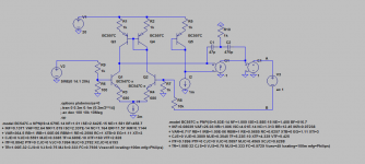
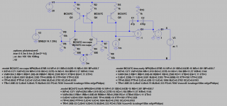
In order to separate the influences, I have used three modified BC547C, see schematic below.
Type BC547C-no-capa has CJE=CJC=0.
Type BC547C-less-early has original capacities, but VAF is multiplied by 100.
Type BC547C-both has both improvements (one should definitely order these devices ;-).
Balanced version: R6=1k, R9=10k (picture names ...-bal)
Unbalanced version: R6=100R, R9=1k (picture names ...-unbal)
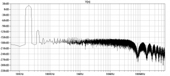
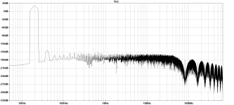
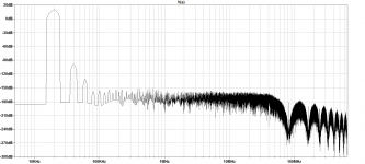
Picture no-capa-bal shows that distortion is as with junction capacities in the balanced circuit, compare post #8434. With unbalanced impedances, picture no-capa-unbal, the second harmonic increases by around 10dB. This is less increase than with junction capacities, compare post #8434, but perhaps not yet the result from SuperTIS simulation. (This was the result from post #8445.)
Pictures less-early-bal and less-early-unbal show that low early effect helps in balanced circuit. For unbalanced impedances, the Miller capacities again give much increased distortion.
Pictures both-bal and both-unbal show that with an almost ideal transistor, all is fine. I repeated both-unbal several times, since I could not believe the result at the beginning.
To summarize, the most influence *in this experiment* stems from the Miller effect, high early voltage is also nice to have.
Finally, I have placed external Miller capacities of 3pF over collector-base junctions of Q1 and Q2, version BC547C-both. Picture both-unbal-ext-miller shows that the distortion really stems from the non-linear Miller effect: the result remains the same.
Matthias
Type BC547C-no-capa has CJE=CJC=0.
Type BC547C-less-early has original capacities, but VAF is multiplied by 100.
Type BC547C-both has both improvements (one should definitely order these devices ;-).
Balanced version: R6=1k, R9=10k (picture names ...-bal)
Unbalanced version: R6=100R, R9=1k (picture names ...-unbal)
Picture no-capa-bal shows that distortion is as with junction capacities in the balanced circuit, compare post #8434. With unbalanced impedances, picture no-capa-unbal, the second harmonic increases by around 10dB. This is less increase than with junction capacities, compare post #8434, but perhaps not yet the result from SuperTIS simulation. (This was the result from post #8445.)
Pictures less-early-bal and less-early-unbal show that low early effect helps in balanced circuit. For unbalanced impedances, the Miller capacities again give much increased distortion.
Pictures both-bal and both-unbal show that with an almost ideal transistor, all is fine. I repeated both-unbal several times, since I could not believe the result at the beginning.
To summarize, the most influence *in this experiment* stems from the Miller effect, high early voltage is also nice to have.
Finally, I have placed external Miller capacities of 3pF over collector-base junctions of Q1 and Q2, version BC547C-both. Picture both-unbal-ext-miller shows that the distortion really stems from the non-linear Miller effect: the result remains the same.
Matthias
Attachments
-
input.asc4.3 KB · Views: 69
-
 both-unbal-ext-miller.png99.7 KB · Views: 101
 -
 both-unbal.png101 KB · Views: 101
 -
 both-bal.png98.1 KB · Views: 98
 -
 less-early-unbal.png102.3 KB · Views: 96
 -
 less-early-bal.png100.7 KB · Views: 103
 -
 no-capa-unbal.png98.5 KB · Views: 263
 -
 no-capa-bal.png99.9 KB · Views: 273
 -
 schem.png124.7 KB · Views: 278
Last edited:
Am I reading this correctly?
1.) Balancing the +IN & -IN impedances improves the distortion.
2.) Using an ideal transistor pair improves the distortion.
3.) Miller effect has the biggest influence on deteriorating distortion.
4.) extrapolating those, then using balanced impedances and high early voltage devices, then the increase in distortion is tolerable even with a higher capacitance input pair.
Does cascoding of the input pair reduce the need for high Early voltage devices?
Last edited:
"As I'm sure you will agree, SPICE is sometimes a handy tool but measurements are the reality."
Bob
It's a bit like masturbating. If you do it often enough you start to think it's the real thing ;-)
In order to separate the influences, I have used three modified BC547C, see schematic below.
Type BC547C-no-capa has CJE=CJC=0.
Type BC547C-less-early has original capacities, but VAF is multiplied by 100.
Type BC547C-both has both improvements (one should definitely order these devices ;-).
Balanced version: R6=1k, R9=10k (picture names ...-bal)
Unbalanced version: R6=100R, R9=1k (picture names ...-unbal)
Picture no-capa-bal shows that distortion is as with junction capacities in the balanced circuit, compare post #8434. With unbalanced impedances, picture no-capa-unbal, the second harmonic increases by around 10dB. This is less increase than with junction capacities, compare post #8434, but perhaps not yet the result from SuperTIS simulation. (This was the result from post #8445.)
Pictures less-early-bal and less-early-unbal show that low early effect helps in balanced circuit. For unbalanced impedances, the Miller capacities again give much increased distortion.
Pictures both-bal and both-unbal show that with an almost ideal transistor, all is fine. I repeated both-unbal several times, since I could not believe the result at the beginning.
To summarize, the most influence *in this experiment* stems from the Miller effect, high early voltage is also nice to have.
Finally, I have placed external Miller capacities of 3pF over collector-base junctions of Q1 and Q2, version BC547C-both. Picture both-unbal-ext-miller shows that the distortion really stems from the non-linear Miller effect: the result remains the same.
Matthias
Your simulation will not show useful result as LTP bases are connected to the ground via very low resistors (R6, R7). You have to insert capacitor in series with R7 and increase R6 to 10k. If you wand to keep DC balance insert capacitor in series with the input source too.
It's a bit like masturbating. If you do it often enough you start to think it's the real thing ;-)
🙂
Also, cascoding the LTP-PSU made a (small) improvement and loading the LTP outputs equally also made a (small) improvement.
Attachments

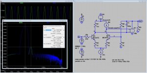
So we still haven't unraveled the root cause of the non-linear Iin?
Jan
No (I think, but smarter people then me should investigate). The attached graph is interesting, it show a FFT of the I(b)'s and it shows that the THD's are (about) equal (about -66dB), and thus it shows that the THD's when equal are canceling each other (the output FFT shows -112dB).
Thus, non equal loading, capacitive or otherwise, anywhere in the diagram, will increase distortion at the output.
Input devices should be matched (even for distortion 🙂).
Attachments
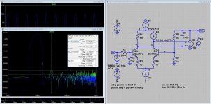
I think Jan has right, one more 🙂 showing the change in output distortion in relation to the source impedance. (it shows that if the source impedances are equal (e.g. 9k) the distortion is much lower).
Attachments
Last edited:
It's a bit like masturbating. If you do it often enough you start to think it's the real thing ;-)
Has everyone discovered the .wav in and .wav out feature of of LTspice?
We can listen to our simulations in 16bit 44.1k.
[emoji23]It's a bit like masturbating. If you do it often enough you start to think it's the real thing ;-)
- Home
- Amplifiers
- Solid State
- Bob Cordell's Power amplifier book