Hi maxzimum
I find it very unlikely that the gain difference has a connection to the amp boards. The gain is determined by two resistors which lead a happy and relatively unstressed life unless the amp is close to full power. Not impossible, but unlikely. And easy to check.
You should make certain it is indeed the amp responsible for the gain difference and put some numbers to it.
Not hard even with only a voltmeter.
What kind of digital inputs does your dac have? In case it is easy to connect a Windows laptop to the dac, checking the gain boils down to running a frequency generator software on the laptop and measuring input and output voltages to and from the amp.
Doable even without a dac using the laptop's built in soundcard but this requires a cable you might not have.
Hi,
Thanks for your quick reply. So besides interchanging interconnects, speakers, etc. to determine the problem, I did the following:
a) Played a 1000hz test tone and measured the output AC voltage with speakers connected. There was a significant difference in L/R (R being lower).
b) I use Roon as playback. In the included DSP, I increased the level of the R channel in small steps till I was at the same voltage as the L Channel. This level was eventually 2.92db. I tested the output at different levels and different test tones and the voltage remains within 0.005 of each other.
What I didn't do was measure voltage to the amp. But interchanging L/R inputs to the amps still causes L to be louder.
Hope this helps.
The BNC inputs are a bit trickier. For a reliable reading the cables will need to be plugged into the amp as the low termination resistance may easily influence the voltage at the end of the cable. I have no idea how easy is to get access to the BNC socket from inside the amp.
In order to measure the input voltage the amp does not need to be plugged in. It is also safer.
In order to measure the input voltage the amp does not need to be plugged in. It is also safer.
It will work provided you use the RCA connection.
With the BNC you will need to either have the amp input connected while measuring or alternatively load the amp side of the cable with a 50ohm resistor. The RCA option appears easier.
If this sounds too mysterious here is the reason.
The preamp almost always has a small resistor in series with the output. The reason is to isolate the effects of capacitive cable loading on the preamp. In the Dartzeel this resistor is most likely 50ohms on the BNC output in order to also match the characteristic impedance to the 50ohm cable. Loading this with another 50ohm on the 108 side will reduce the voltage by 50%. As the above is mostly speculation it is safer to just use the high impedance connection where the corresponding reduction of voltage with the amp connected is negligible.
I'm a bit confused.. Just to be clear, you want me to measure the voltage on the L/R RCA plugs coming from the preamplifier at the Amplifier end. Correct?
Also could you tell me which are the 2 resistors responsible for the gain? I could check these also.
Thanks
Also could you tell me which are the 2 resistors responsible for the gain? I could check these also.
Thanks
Last edited:
Just to be clear, you want me to measure the voltage on the L/R RCA plugs coming from the preamplifier at the Amplifier end. Correct?
Yes. And then measure the output to the speakers. The ratio of the two will give you the voltage gain of the amp. Which should be around x22.
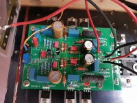
There are actually 4 resistors per channel that set the gain. It is possible to test them without desoldering but the values you read will depend on whether your amp has the "network" mod (supercaps).
The 360 ohm resistors will read close to that value irrespective of the mod and these are anyway very unlikely to stray.
The 7.5k resistors will read 7.5k if your amp has the mod or around 3.9k if it does not.
If any resistor has indeed changed its value it should be easy to detect.
Attachments
Hi,
Here are my measurements (RCA):
Input to Preamp - L/R - 0.039
L input to Amp - 0.108
L Speaker Out - 1.430
R Input to Amp - 0.107
L Speaker Out - 2.110
I do have the SCNP network.
I will check the resistors (going to be bit of a project getting to them) and repost.
Many thanks for the information. I truly appreciate your help.
I mixed up the values. Correct values are:
R input to Amp - 0.108
R Speaker Out - 1.430
L Input to Amp - 0.107
L Speaker Out - 2.110
Your amp's left channel has a voltage gain of x19.7 - exactly the same as my amp but the right channel is only x13.2.
If the resistor hypothesis holds true, one of the 7.5k resistors should measure closer to 4.7k, or alternatively and less likely the 360R would measure much higher.
Let's hope this is all there is to it as most other repairs are more involved and will require dismantling the board from the sink.
Such a dramatic change in resistance is not too common. In fact i don't recall seeing anything like it in an unstressed resistor.
Next in line would be the supercap. I have no idea how realistic is to expect its ESR to have suddenly climbed up a couple hundred ohms, but this is what Tokin's app note on supercaps says:
" The electrolyte of these SuperCapacitors is sealed with material such as rubber. When you use the capacitors for a long time at high temperature, the moisture of the eleotrolyte evaporates and the equivalent series resistance (E.S.R.) increases. The fundamental failure mode is the open mode depending on E.S.R. increase."
Hello !
I think this is the solution:
1mV Midpoint Active Servo Technology Protection Circuit Base on Dartzeel NHB-108 822933248331 | eBay
I think this is the solution:
1mV Midpoint Active Servo Technology Protection Circuit Base on Dartzeel NHB-108 822933248331 | eBay
Many thanks to @analog_sa for helping me diagnose and sort the problem with my amp. Much grateful!
All the best to everyone on here!
So what was it in the end? Resistor drift?
Problem with the supercapacitor which needs to be replaced.So what was it in the end? Resistor drift?
Bypassing it has done the trick for now.
- Home
- Amplifiers
- Solid State
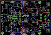
- Dartzeel amp schematic - build this?