This is turning into a fine, creative conversatioon. Fruitfull. Something like this has happened in "Krell KSA-50 build this" thread a number of years ago. This thread has the potential to bring us to success.
I guess it would be the best that experts here compare the existing 458 circuits and reach conclusion on the question: which schematics is the best starting point and try to polish it and go forward with topology of the board.
It is counterproductive that everyone stands on his side claiming that others are wrong. Let us first see what the proposed circuits have in common and what is missing.
Preparedness for collaboration and listening to each other is the right way to go.
Andiamo Domenico!
This is turning into a fine, creative conversatioon. Fruitfull. Something like this has happened in "Krell KSA-50 build this" thread a number of years ago. This thread has the potential to bring us to success.
I guess it would be the best that experts here compare the existing 458 circuits and reach conclusion on the question: which schematics is the best starting point and try to polish it and go forward with topology of the board.
It is counterproductive that everyone stands on his side claiming that others are wrong. Let us first see what the proposed circuits have in common and what is missing.
Preparedness for collaboration and listening to each other is the right way to go.
Andiamo Domenico!
I AGREE ,
but,
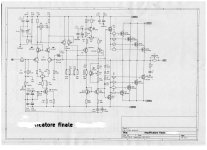
I think that a scheme, speaking not of elementary and closed NAIM-like schemes, already says a lot:
- an open loop scheme already lets you think how it can sound, with its pros and cons, I mean, not in detail.
The scheme of 108, I repeat, but in my humble opinion, has many limits, perhaps too many.
The scheme of the 458 that I posted, however, gives hope that some limits of 108 can be overcome.
The supercap remains, which is on the signal, but something you can do, I think, with an excellent bypass.
I add :
if I stabilize EVERYTHING, we still improve and save those expensive cans that are often unhealthy
This scheme offers excellent results, but these results can vary greatly depending on how the PCB is made, on the power supply and its positioning and also on some resistances (not complete scheme!!)
Hardly this scheme, although not in a definitive form, but I could also post it, few details change, but ............., nothing secret! , will never have the fascinating performances of medium and mid high of 108, for clear reasons, it can be more precise and concise, but it lacks charm.
However low, medium low, speed, dynamics and articulation of the low and medium low are of great level
Attachments
Last edited:
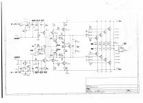
domenico, apparently this schematic has nothing to do with darTZeel: different topology (no cfb), input is FET diff pair, NFB from the output...
INDEED.
One with a high feedback, the second (108/458) with an open ring.
This is to say that, in my opinion, the typology of a scheme already says many things about how it can sound, not everything, but a lot.
THEN the refinement work on certain technical parameters that I consider fundamental.
Clear that to insist, EXAMPLE, with a NAIM type scheme, well, you can't do much, quite the contrary.
The high feedback scheme, PLEASE NOTE, has no compensation and no capacitor on the signal and no limitations, therefore, it should be limited and fairly faithful
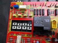
Read the above post of our friend analog_sa again.It would be really, really nice if you can share a couple of the multiple pictures you have no doubt takenOr at least one of the component side.
I am reposting this because this is the essence: reliable, first hand data as the basis for the future work. In KSA-50 thread there was a member "bra" who contributed the schematic, then everything went well. So please, as much photos, schematics, reverse engineering as possible.
This is an European thread. Can we deliver?
Are here Poles and Hungarians who have worked on this?
Erikovsky, please, tell us more!


Last edited:
Let us first see what the proposed circuits have in common and what is missing.
The two circuits are identical despite our friend's Domenico insistence they are not
Whether there is an input coupling cap or an offset nulling circuit is immaterial, as these require just a couple of extra pads.
Domenico's interpretation assumes there is second lower voltage PS with the only function to feed the CCS, which even to me appears wasteful beyond belief. If that particular part of the circuit requires improving, a cascoded ccs would be a much more sensible solution. Perhaps Domenico can throw some light on his reasoning here. Highly unlikely the genuine article has any such niceties.
Domenico's other suggestion - to power the entire front end (VAS) from an independent, regulated supply makes a lot more sense. Again, i find it unlikely the original provides for this but it is only a question of two jumpers on the board to allow for an additional front end PS.
So, it appears the Hungarian fantasy is more than a fantasy and someone has already peeked under the bonnet
I am certainly surprised that this circuit is simpler than the 108 and may well represent the simplest amp of such power ever.
Domenico, please stay tuned, erikovsli, nalog_sa, selfy, mocenigo and others let us try.you say they are perfectly identical?
Okay
I understand how it is: if you want to be exceptional you have to have "ego". I understand that all of you have own unique ideas. But over time I have realised it is much more important to be able to sacrifise own "I" to succeed as a part of the team. So lets be rational and get togrther to see what can be done. Is it possible to draw a schematics we all agree on? May I help? I am ready to invest some money for material costs. Please PM to me if interrested.I am ready to pay for components to assemble a prototype. I am learning quickly and I might contribute to the design in the future,
you say they are perfectly identical?
Okay
Yes, for all that matters, Even the compensation is the same. Saying OK does not really make a point.
Domenico, please stay tuned, erikovsli, nalog_sa, selfy, mocenigo and others let us try.
I understand how it is: if you want to be exceptional you have to have "ego". I understand that all of you have own unique ideas. But over time I have realised it is much more important to be able to sacrifise own "I" to succeed as a part of the team. So lets be rational and get togrther to see what can be done. Is it possible to draw a schematics we all agree on? May I help? I am ready to invest some money for material costs. Please PM to me if interrested.I am ready to pay for components to assemble a prototype. I am learning quickly and I might contribute to the design in the future,
I believed and hoped to be clear, always to my taste, like everyone else.
Anyway, ask and answer, of course, according to my experiences and tastes and technically as well.
I was ALMOST sure I sent interesting messages
Yes, for all that matters, Even the compensation is the same. Saying OK does not really make a point.
it makes sense in relation to what I read from your writings, without offense, of course
so you claim that these 2 patterns are identical?
because we talk about this
one
Attachments
Last edited:
Attachments
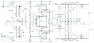
mmmmmhhhh

watch out for the Chinese, they also sell you the mother of others
I have noticed this trend in China: they add "features" to clones: power supplies on the same board, speaker protection etc. Who knows why, perhaps to prevent legal issues. But, as far as I understand, NHB-108 clone board is 1:1 and it sounds just fine for me. With original components this could be an amplifier to have.The volume discount is a killer. You buy 15 and you save $1.80. That's one tough seller.
This appears to be a bridge amp, so no matter where it started it got extensively redesigned.

Last edited:
mmmmmhhhh
watch out for the Chinese, they also sell you the mother of others

One more reason to have our European clone. What about Italian-Hungarian collaboration?
- Home
- Amplifiers
- Solid State
- Dartzeel amp schematic - build this?