Now the thread issue is resolved, perhaps offering up an idea would be in order.
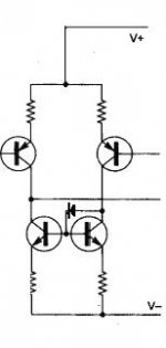
Current Mirrors. They rely on two transistors with identical Vbes and emitter degeneration, delivering an output current on one side driven from a sensing current on the other side.
However, there's a problem. The sensing side configures the transistor as a diode, but the output side configures its device as a transistor.
These two devices therefore have different transfer functions. That is, the absence of a depletion layer on the diode connected side means that the output current will not precisely track because the Vbe's differ with current.
How to fix this?
Instead of running a simple link from collector to conjoined bases, connect the collector on the sensing side with a forward biased diode to the two bases. Bases remain joined, as before.
This way both transistors are operating with depletion layers, viz, as transistors, and the transfer functions are much closer to being identical. Thus, linearity is improved. The Widlar current mirror achieves this, but by adding another transistor. This is simpler.
Hugh
AKSA said:Now the thread issue is resolved, perhaps offering up an idea would be in order.
Current Mirrors. They rely on two transistors with identical Vbes and emitter degeneration, delivering an output current on one side driven from a sensing current on the other side.
However, there's a problem. The sensing side configures the transistor as a diode, but the output side configures its device as a transistor.
These two devices therefore have different transfer functions. That is, the absence of a depletion layer on the diode connected side means that the output current will not precisely track because the Vbe's differ with current.
How to fix this?
Instead of running a simple link from collector to conjoined bases, connect the collector on the sensing side with a forward biased diode to the two bases. Bases remain joined, as before.
This way both transistors are operating with depletion layers, viz, as transistors, and the transfer functions are much closer to being identical. Thus, linearity is improved. The Widlar current mirror achieves this, but by adding another transistor. This is simpler.
Hugh
Hello Hugh
A 1N4148 would do or need a faster diodes ?
Thank
Bye
Gaetan
It should look like that;
Attachments
Ahh, a subtle truth is gained.🙂
?? A question , what diode , general purpose(1n4001??)
and, would one HEAR a difference.
I guess I'll be "floatin" my current mirror bases to add a diode
in a few days. Thanks hugh.
?? A question , what diode , general purpose(1n4001??)
and, would one HEAR a difference.
I guess I'll be "floatin" my current mirror bases to add a diode
in a few days. Thanks hugh.
Yes Ostripper,
There is a difference sonically. Far superior decay, which I take to mean more resolution. Translates to slightly improved imaging, too.
Hugh
There is a difference sonically. Far superior decay, which I take to mean more resolution. Translates to slightly improved imaging, too.
Hugh
Hi, AKSA,
I once tought about this about current mirror. The sensing side has almost constant Vce=0V6. But the mirror side has bigger Vce. They both will have different Early effect voltage. How far this will affect the perfectness of a current mirror?
I once tought about this about current mirror. The sensing side has almost constant Vce=0V6. But the mirror side has bigger Vce. They both will have different Early effect voltage. How far this will affect the perfectness of a current mirror?
ostripper said:Ahh, a subtle truth is gained.🙂
Hardly.
That diode only has potential to make the current mirror linearity worse – in fact I just proved my hunch in LTspice – at 20kHz the LTP non-linearity of a “Blameless” increased significantly (~50%).
It is sub optimal to add a diode in the signal path of a linear circuit like this such that it is forward biased with a current as low as the base currents of the current-mirror transistors.
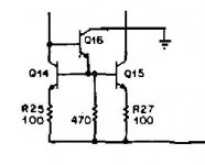
If you want to better the current mirror by any significant amount then your options are the 4 transistor Widlar or the 3-transistor version attached below. Note the 470-ohm resistor? This ensures high frequency linearity by developing an adequate quiescent emitter current for Q16.
And no, this 470-ohm resistor is not a potential fix for the diode fudge.
Cheers,
Glen
Attachments
By G. kleinschmidt : That diode only has potential to make the current mirror linearity worse – in fact I just proved my hunch in LTspice – at 20kHz the LTP non-linearity of a “Blameless” increased significantly (~50%).
Confirmed... But the "truth" I was mainly interested in was
the psychoacoustical one. (how will it sound??)
I guess the only way to see would be to actually add
the diode (or the widlar circuit) to the real thing, crank it
up , and let the ears have at it.
So, it comes down to linearity vs. acoustics.
Would it not be nice to be able to listen to the output
of LT spice 😎 Lt spice w/ headphone jack....
Give me a break.. a compliment will get you much more than anBy balaboo : ego massaging
attack. Like maybe a friend.
OS
Kleinschmidt,
I expected your usual whining comment. You have PSpiced it, not built it, never heard it..... get on with it man, do the work, and learn to trust your ears.
This gem is found in a 1999 Halcro US patent, so I would suggest you refer your august arguments with Bruce Candy. After all, his amps are reputedly amongst the best in the world, and they boast extremely low distortion, which would be mandatory for you. Good enough for him and the world, it seems. Where do you stand? Where is your commercial amplifier? How many patents in this area do you hold?
One can only speculate on the state of mind of someone who appears to know it all, and is so certain of everything he does and says. Upbringing, genetics, who knows. The contempt you radiate is self-damaging, and a complete waste of energy, particularly for one who in his own mind at least, is very clever. Time you behaved with a dignity befitting your intellect......
AKSA said:Kleinschmidt,
I expected your usual whining comment. You have PSpiced it, not built it, never heard it..... get on with it man, do the work, and learn to trust your ears.
This gem is found in a 1999 Halcro US patent, so I would suggest you refer your august arguments with Bruce Candy. After all, his amps are reputedly amongst the best in the world, and they boast extremely low distortion, which would be mandatory for you. Good enough for him and the world, it seems. Where do you stand? Where is your commercial amplifier? How many patents in this area do you hold?
One can only speculate on the state of mind of someone who appears to know it all, and is so certain of everything he does and says. Upbringing, genetics, who knows. The contempt you radiate is self-damaging, and a complete waste of energy, particularly for one who in his own mind at least, is very clever. Time you behaved with a dignity befitting your intellect......
Thanks for the predictable diatribe.
You diode idea for improving the current mirror linearity is nonsense. I explained why and provided a workable alternative.
Deal with it
G.Kleinschmidt said:
Hardly.
That diode only has potential to make the current mirror linearity worse � in fact I just proved my hunch in LTspice � at 20kHz the LTP non-linearity of a �Blameless� increased significantly (~50%).
It is sub optimal to add a diode in the signal path of a linear circuit like this such that it is forward biased with a current as low as the base currents of the current-mirror transistors.
If you want to better the current mirror by any significant amount then your options are the 4 transistor Widlar or the 3-transistor version attached below. Note the 470-ohm resistor? This ensures high frequency linearity by developing an adequate quiescent emitter current for Q16.
And no, this 470-ohm resistor is not a potential fix for the diode fudge.
Cheers,
Glen
WRT addition of diode, at this point I disagree Glen.
I spiced up a quick circuit and did fft on OP current linearity.
The LTP needs to be run at decent degeneration and at very
low AC current swing to clearly show the mirrors effect.
However, once the surrounding circuitry is linearised sufficiently
so it 'disappears' from the results, the diode can half the distortion
depending on operating points.
The 3 transistor version mentioned is the obvious next step to
isolate mirrors base currents and add some further improvements.
Stay calm guys! Both of you can be a lot more pleasant.
By the way , the work "nonsense" is very close to insulting enought fora trip to the bin. You know that Glenn.

By the way , the work "nonsense" is very close to insulting enought fora trip to the bin. You know that Glenn.
I tend to agree with Glen on this, because the 'mirror' transistor is supposed to be a diode. However, IF there is an advantage of adding an extra diode, then a transistor follower should even be better, as it creates the same conditions for the 'mirror' transistor, but would be more linear.
After reading about it..
http://www.odyseus.nildram.co.uk/RFIC_Theory_Files/Current_Mirror.pdf
I guess I'll try the diode ,buffered widlar (Glen's), and finally,
as a reference ,a standard mirror.
Halcro...WOW , 20-50K$ amps , he sues any who violate his
IP , still I found some schematics (and the diode) in an amp
that was really drooled over in the 90's.
PS .. best to make a pluggable SMT "daughtercard" for input
section , play around with cheap $.01-10c devices..😎
OS
AKSA said:This gem is found in a 1999 Halcro US patent(...)
This trick seems to be specific to his particular design though. The CE transistor of his VAS has a diode in series with its base. So the idea was apparently to match the Vcb of the two transistors in the mirror, given that odd VAS configuration (VAS diode seeing base current of VAS CE stage, mirror diode seeing base current of mirror stage).
AKSA said:Where is your commercial amplifier?
Well, Candy ripped off the design of the FET error correction circuitry (including its compensation technique) from Bob Cordell, who has no commercial amplifier AFAIK. And Bob got the original concept from Hawksford, who has no commercial amplifier either. There's plenty of hacks who have commercial audio products, so that doesn't mean anything. Just look at Audio Circle for examples.
Terry Demol said:
WRT addition of diode, at this point I disagree Glen.
I spiced up a quick circuit and did fft on OP current linearity.
The LTP needs to be run at decent degeneration and at very
low AC current swing to clearly show the mirrors effect.
However, once the surrounding circuitry is linearised sufficiently
so it 'disappears' from the results, the diode can half the distortion
depending on operating points.
The 3 transistor version mentioned is the obvious next step to
isolate mirrors base currents and add some further improvements.
I suggest your method of simulation is suspect. This issue is with the linearity of the circuit at high frequency when the LTP is NOT operating at a "low AC current swing".
You simply cannot expect a high degree of HF linearity (working against the BJT junction capacitances) from a diode forward biased with a few tens of uA.
As for this allegedly being a “Halcro concept”; If true then all I will say is that Bruce Candy is not unknown for passing the occasional furphy in his patent applications.
And anyway the current mirror circuit which typically uses a diode in this configuration to raise the collector voltage of the “diode” BJT does so in conjunction with another diode to act as an anti-saturation clamp (see the Stocichino (spelling?) fast amp. However this is a different kettle of fish.
Cheers,
Glen
G.Kleinschmidt said:As for this allegedly being a “Halcro concept”; If true then all I will say is that Bruce Candy is not unknown for passing the occasional furphy in his patent applications.
Yeah, that was my impression also. What's with that diode in series with the base of the VAS CE amp anyway? One could see why he'd put one in the emitter, to make sure the mirror has enough Vcb under high-current conditions. But the base? Just makes the behavior more dependent on the BJT beta than it should be.
I have not seen any diode into base of any vas transistor of aksa
not in those schematic versions shown for free
but maybe it is in some original schematic, those we get if we order the kit
The only diode I can see used is one extra rectiifier for VAS/Input supply rail.
I can not think hugh would put such a diode.
No such thing in this conceptual attachment of hugh:
http://www.diyaudio.com/forums/showthread.php?postid=1652112#post1652112
I've attached a conceptual schematic of the AKSA. Some details are missing, of course, ......
- Home
- Amplifiers
- Solid State
- Current Mirror Discussion