Hi Mooly,That's great. Now you can really give it a good listen 🙂 Those caps are both fitted differently to what you might expect given a quick look at the circuit.
-/+ 60 volts rails would possibly need Q3 and Q5 uprating or at least fitting with clip on heat sinks. They would certainly run hot and be dissipating around 400mw each at idle. The 10k should be fine as it is as long as a 0.5 watt part is fitted.
Yes, I hadn't thought about the small transistors. I just went and felt them and they run pretty hot just at the +-45V rails it is running at right now. Maybe need TO-126 there for higher rails? I don't really need the extra power. I just have some extra transformers in that range.
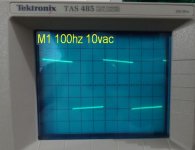
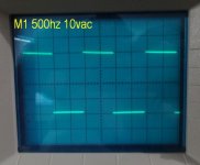
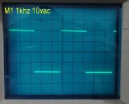
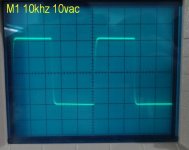
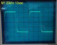
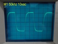
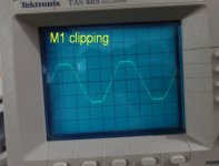
Here are some scope shots for those who like this sort of thing.
Blessings, Terry
Attachments
Looking good 
Some of latest versions of the MJE340/350 seem pretty decent, I've had some from manufacturer CDIL and was quite impressed generally. Its very difficult suggesting devices because you need to be sure you get genuine parts and some are hard to source.
Some of latest versions of the MJE340/350 seem pretty decent, I've had some from manufacturer CDIL and was quite impressed generally. Its very difficult suggesting devices because you need to be sure you get genuine parts and some are hard to source.
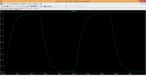
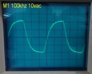
Interesting to compare the simulation result against your real version. Edit the input filter (4k7 and 150pf) is the main reason for the HF roll off. Its deliberate as I'm not a fan of leaving the input open to wideband noise and hash.
100kHz.
I don't pay too much attention to anything above 10khz. It is only there to give an idea of how well the circuit is running. I can't hear past 10khz.
if you reform this cap and try measuring leakage you will find out quite quickly whether it is manufactured correctly or not.-3.6V
6mV
Please change those caps and fit new replacements as marked on the board.
With the cap fitted the way they are I have -6V on the output of the servo. With them fitted per the schematic I have -10.5V on the servo output. With the caps fitted the way they are I have basically zero offset. With them fitted per the schematic I saw as much as 27V offset. Now it may not be the cap that is causing the issue. It might just be that the cap being inverted is stopping the voltage at the emitter of Q1 from rising too high. Perhaps there is something else that is driving the offset to rise and the inverted cap is clamping it down. I don't know. What I do know is that it didn't work before and now it is. I don't mind trying different scenarios if you feel like doing to work but changing the cap back is not going to solve it though it may help reveal it. This is kind of tough with us living in drastically different time zones but I'm in no hurry. This is a hobby after all.
Blessings, Terry
Worth checking the others from that batch in case your whole stock is incorrectly manufactured.
I repeatedly suggest reform and check leakage in these pages.
if you reform this cap and try measuring leakage you will find out quite quickly whether it is manufactured correctly or not.
Worth checking the others from that batch in case your whole stock is incorrectly manufactured.
I repeatedly suggest reform and check leakage in these pages.
The caps were OK. I was getting that voltage swing because I had the input cap reversed. Inverting the NFB cap was blocking the path to ground and stopping the swing but at the price of the circuit not working at its best. I'm just starting to get my head wrapped around the AC path in a circuit. I get so wrapped up in measuring DC throughout the circuit I forget that the signal is AC and that its direction through the circuit is important. This was a good lesson to learn.
Blessings, Terry
:
Mr Terry Sir,,All; audio is AC Which rides piggyback on DC,,a good exsam,ple of this is your run of the mill telephone keep up weith your great builts..Joe
That's great. Now you can really give it a good listen 🙂 Those caps are both fitted differently to what you might expect given a quick look at the circuit.
-/+ 60 volts rails would possibly need Q3 and Q5 uprating or at least fitting with clip on heat sinks. They would certainly run hot and be dissipating around 400mw each at idle. The 10k should be fine as it is as long as a 0.5 watt part is fitted.
Mr. Karl,
as per above post, if I want to use 60V rails, what can be used for Q3/Q5 with small PCB heat sinks. Also what is power o/p 4 ohm, gain, i/p RMS voltage clipping, etc.
Octave1
-/+ 60 volts rails are very high for an amplifier like this. The old MJE340/350 should work well here but unless you simply have to use an existing high voltage transformer I wouldn't really recommend it by choice.
The difference in perceived loudness from an amp on -/+45 volts and one on -/+60 volts is minimal to the point you wouldn't notice. Most fairly loud listening is done in the one to two watt region.
The voltage gain of the amp is approx. '48' which means that you need just under 600 mv rms at the input to achieve a nominal 100 watts rms into 8 ohm. That is really pushing it too far though for the flat pack outputs specified. If you use T03 style devices then its just about do-able as they have better heat transfer to the heatsink. Even then 50 to 55 volts would be better as an absolute maximum.
True 4 ohm resistive loading for any amplifier is tough (when you mean full power testing into 4 ohms) and -/+ 60 volt rails are too high to support very high output levels. You need multiple output pairs for that.
For practical home use, there is no problem with loads that dip down to 4 ohms and below. Full power testing, and specifying an amp accordingly is a totally different ball game... but that applies to any design.
Think very carefully whether you need to use such high voltage rails though.
Thanks you Mr. Karl for your answers. Sorry I should have been more clear in my questions.
1. I want to use 2 pair version(Alexmm version) but will do my own layout, and hence I want it to have capability to handle 60V at 4 ohm for music and never for full power test/square wave test. may be subwoofer (home) who knows, if bass is good🙂.
2. Yes I have transformer to give 56V rated after rectifier but gives >60 to 62 V unloaded, hence want to use this. poor regulation?, but cash already spent:-(.
3. Nominal Power in 4 ohms, (for bragging to friends 🙂). I know there will be drop due to PSU/regulation/ rail sagging and being mosfets, they will give less power than BJT, i dont know to calculate for lateral mosfet, first lateral mosfet project.
Realistically you are probably looking at 150 wrms into 4 ohms if you use two pairs of outputs and with your PSU. The laterals drop around 10 to 12 volts at their max rated current (7 amp each for these).
The bass is very good 😉
The bass is very good 😉
Realistically you are probably looking at 150 wrms into 4 ohms if you use two pairs of outputs and with your PSU. The laterals drop around 10 to 12 volts at their max rated current (7 amp each for these).
The bass is very good 😉
Thank you Mr. Karl. I will post here my layout and progress.
Of all the simple amps on this forum, I have always liked this one as I know it sounds very musical. Karl's rejection of intense measuring gets my vote..... Some of Bigun's amps are very, very good too, but the amps I see here with high parts counts and very low THD leave me cold - a bit like the sound they make on my favourite music.
Hugh
Hugh

Words of Hugh sir, have convinced me to forget the plan to use high voltage for this amp and build it as it is.Of all the simple amps on this forum, I have always liked this one as I know it sounds very musical. Karl's rejection of intense measuring gets my vote..... Some of Bigun's amps are very, very good too, but the amps I see here with high parts counts and very low THD leave me cold - a bit like the sound they make on my favourite music.
Hugh
Thank you!.
To Mr. Karl
I will build this based on alexmm layout. One thing, does the input cap needs to be high quality polarized or can I use nichicon muse series non-polarized? I have plenty of those.
Building it as designed is always the best plan.
The input cap has around 6 volts across it so bear that in mind (and watch the polarity, its the opposite way around to most amps). There are no special requirements for the cap, in fact many boutique parts are at a disadvantage in being physically large which means that as well as taking up space, they are more prone to pick up stray radiated fields and interference. I'm afraid I'm not a believer (for the most part) when it comes to so called audiophile components. Use top 'commercial quality' and you will be fine.
The input cap has around 6 volts across it so bear that in mind (and watch the polarity, its the opposite way around to most amps). There are no special requirements for the cap, in fact many boutique parts are at a disadvantage in being physically large which means that as well as taking up space, they are more prone to pick up stray radiated fields and interference. I'm afraid I'm not a believer (for the most part) when it comes to so called audiophile components. Use top 'commercial quality' and you will be fine.
Mr. Karl, As you have said in thread, a delay and speaker protection circuit is essential. I tried reading that thread but got lost. Do you have as built schematic of the protection circuit involving SSR that was fitted in your amplifier?
- Home
- Amplifiers
- Solid State
- My MOSFET amplifier designed for music