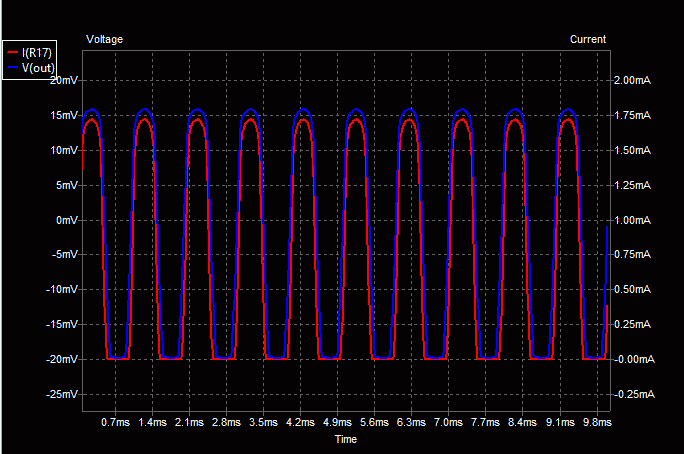
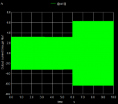
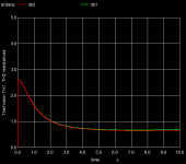
F6 minimal, simulation results
mean output voltage (dc offset)
mean: -0.00348107
output power 1 kHz load 8 Ohm
21.5 W
output power 1 kHz load 4 Ohm
27.2 W
damping factor 4 at 8 Ohm
mean output voltage (dc offset)
mean: -0.00348107
output power 1 kHz load 8 Ohm
21.5 W
output power 1 kHz load 4 Ohm
27.2 W
damping factor 4 at 8 Ohm
Attachments


Hi hvogt,
Thank you for your efforts. As a user of Kicad I appreciate it very much.
Best regards,
Mogens
Thank you for your efforts. As a user of Kicad I appreciate it very much.
Best regards,
Mogens
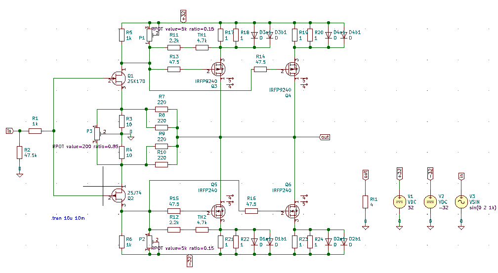
Help to get simulating using KiCad in windows
I tried to simulate the attached circuit (F5 v2) but it only shows a very small output voltage and only a few mA of drain currents in the IRFP240.
.
Since this was my first time trying to run ngspice via KiCad I am stuck. I tried updating to the latest KiCad v5.1.6 (64 bit for Windows) but still the same. I found R8 and R9 shorting P3 but changing that didn't help, and I found Q2 has a different pin connection order (SGD) to Q1 (DGS) so flipped Q2 but still no output voltage (circuit mods below).
 These are error messages
I was hoping to run the thermal simulations in the following posts but the same circuit changes to Q2 and R8/9 appear to be needed.
The F6 version has a 'readmeF6.txt' file that says
Any help would be much appreciated for a Win 10 user.
Hi Holger,Attached you will find a KiCAD Demo ready for simulation. ...
I tried to simulate the attached circuit (F5 v2) but it only shows a very small output voltage and only a few mA of drain currents in the IRFP240.
.
Since this was my first time trying to run ngspice via KiCad I am stuck. I tried updating to the latest KiCad v5.1.6 (64 bit for Windows) but still the same. I found R8 and R9 shorting P3 but changing that didn't help, and I found Q2 has a different pin connection order (SGD) to Q1 (DGS) so flipped Q2 but still no output voltage (circuit mods below).
Code:
unrecognized parameter (cthj) - ignored
Warning: Model issue on line 16 : .model irfp9240  vdmosp ( vto=-4 kp=8.8 lambda=.003 theta=0.08 ksubthres ...
unrecognized parameter (xti) - ignored
unrecognized parameter (tcvth) - ignored
unrecognized parameter (texp0) - ignored
unrecognized parameter (rthjc) - ignored
unrecognized parameter (cthj) - ignored
Error on line 46 : mq3 out net-_q3-pad2_ net-_d3a1-pad1_ nc_01 nc_02 irfp9240
too many nodes connected to instance
Error on line 47 : mq5 out net-_q5-pad2_ net-_d1a1-pad2_ nc_03 nc_04 irfp240
too many nodes connected to instance
Error on line 48 : mq4 out net-_q4-pad2_ net-_d4a1-pad1_ nc_05 nc_06 irfp9240
too many nodes connected to instance
Error on line 49 : mq6 out net-_q6-pad2_ net-_d2a1-pad2_ nc_07 nc_08 irfp240
too many nodes connected to instance
Doing analysis at TEMP = 27.000000 and TNOM = 27.000000
Warning: v3: no DC value, transient time 0 value used
Initial Transient SolutionThe F6 version has a 'readmeF6.txt' file that says
Maybe this is required but I can't find the file 'spice.rc'In addition you may place the attached file 'spice.rc' into your home directory. This is required to enable Eeschema/ngspice reading PSPICE compatible device models.
Any help would be much appreciated for a Win 10 user.
Attachments
Last edited:
ngspice-32 required for VDMOS electro-thermal simulation
The error message tells it: the thermal model parameters are not recognized and the 5 VDMOS nodes are not available: With KiCAD 5.1.6 you will get ngspice-31. But ngspce-32 is required. In addition: the Eeschema/ngspice interface is rather limited. So for many advanced simulations plain ngspice has an advantage. What to do:
Upgrade ngspice within KiCAD/Eeschema (Windows 10) by downloading ngspice-32_dll_64.zip from ngspice - Browse /ng-spice-rework/32 at SourceForge.net. Open the zip file, go to ngspice-32_dll_64.zip\Spice64_dll\dll-mingw\ and extract msys-ngspice-0.dll into your KiCAD installation directory (I use C:\Program Files\KiCad\bin\, which requires admin rights for extracting). Then go into C:\Program Files\KiCad\bin\, rename libngspice-0.dll (the ngspice-31 dll) to libngspice-0-orig.dll, then rename msys-ngspice-0.dll (the ngspice-32 dll) to libngspice-0.dll. Put the file spice.rc into your HOME directory (mine is C:\Users\holger). Re-start KiCAD/Eeschema.
Then you may run the simulator from Eeschema in the usual way: File->Open->my.sch->Tools->Simulator->Run
Standard ngspice offers many more simulation types. To install it, download ngspice-32_64.zip from ngspice - Browse /ng-spice-rework/32 at SourceForge.net and extract it to C:\ on your computer. You then will have ngspice.exe in C:\Spice64\bin.
From within Eeschema plain ngspice may be started by: File->Open->my.sch->Tools->Generate Netlist File...->Spice->Check 'Default format'->Enter C:\Spice64\bin\ngspice.exe into 'Simulator command:' text box->Run Simulator. Ngspice will now execute the simulations as prescribe in the script file
I have attached a new project zip file PassLabF5-4.zip to this message. It has a README file F5readme.txt and it includes spice.rc. The projct files are F5TurboV2thermal-short.sch and F5TurboV2thermal-ac.sch.
Attachments
Last edited:
electro-thermal simulation
Some thoughts on electro-Thermal simulation are gathered at ngspice tutorial for electro-thermal simulation (not yet complete).
Some thoughts on electro-Thermal simulation are gathered at ngspice tutorial for electro-thermal simulation (not yet complete).
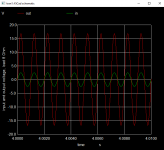
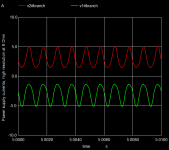
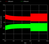
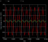
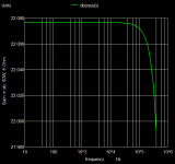
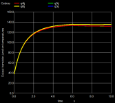
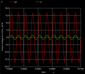
F5 Turbo V2 simulation results
Some simulation results (for setup see #205):
The simulation of this amplifier yields excellent results: 50 W into 8 Ohm, 98 W into 4 Ohm, damping factor 58, voltage gain 22 dB (a factor of 12), all simulated at 2 V peak (1.41 V rms) and 1 kHz input.
Some simulation results (for setup see #205):
The simulation of this amplifier yields excellent results: 50 W into 8 Ohm, 98 W into 4 Ohm, damping factor 58, voltage gain 22 dB (a factor of 12), all simulated at 2 V peak (1.41 V rms) and 1 kHz input.
Attachments
-
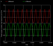
 F5-Suppl-curr-detail.png12.9 KB · Views: 134
 -
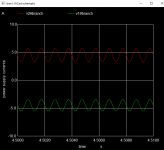
 F5-Suppl-curr.png8.3 KB · Views: 128
 -
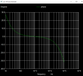
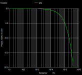 F5-phase.png8.9 KB · Views: 129
 -
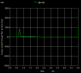 F5-Out-Curr-Zero-in.png9.8 KB · Views: 132
 -
 F5-Out-Curr-1Khz.png8.8 KB · Views: 137
 -
 F5-In-Out-100W.png13.3 KB · Views: 145
 -
 F5-gain.png9.5 KB · Views: 132
 -
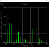
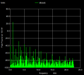 F5-fft-100W.png10.1 KB · Views: 136
 -
 F5-Thermistors-TH1TH2.png9.4 KB · Views: 135
 -
 F5-Tr-Temp.png11.7 KB · Views: 126
Hi Holger,... But ngspce-32 is required. In addition: the Eeschema/ngspice interface is rather limited. So for many advanced simulations plain ngspice has an advantage. What to do: Upgrade ngspice within KiCAD/Eeschema (Windows 10) by downloading ngspice-32_dll_64.zip ...
I have attached a new project zip file PassLabF5-4.zip to this message. It has a README file F5readme.txt and it includes spice.rc. The projct files are F5TurboV2thermal-short.sch and F5TurboV2thermal-ac.sch.
I now have the 'F5 thermal' working now including running the script. Thanks so much!

Those steps will be useful for may LTspice users who would like to try ngspice using KiCad GUI on Windows.
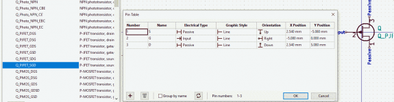
Re: Q2 pin assignment.
It appears from this that ngspice interprets all FETs pins 1,2,3 as D,G,S respectively. That's irrespective of the pin assignment in KiCad Library Symbol editor (below) - is this intentional?
Also, your circuits have R8 and R9 shorted. I think trimpot P3 needs this open to work properly.
Attachments
R8 and R9 shorted
Yes, that's wrong. Opening the short will require a different trimpot setting for P1 and P2. The influence of P3 seems to be overly strong. I will upload another corrected schematic later.
Concerning pin numbering
KiCAD is a layout tool, taking care of vendor supplied pin configurations and pin numberings, typically linked to footprints.
ngspice has a fixed D G S sequence for MOS devices, and also fixed pin sequences for all other devices.
You need to have some translation between the two. This is served during the Spice model setup by defining the 'Alternate node sequence' in Eeschema. I have made a description how to handle this in KiCad Eeschema as GUI for ngspice, tutorial for setting up the simulation, not for MOS only, but for all devices. Especially this is a nuisance for diodes, where Eeschema nearly always has the inverted pin numbering compared to ngspice, and you definitely have to define the 'Alternate node sequence' 2 1.
ADS is currently available free for 3 months due to Corona home office.
Or to get you on the hook.
If you always wanted to compare your models against the industry standard
it may be now or never.
< Innovationen an jedem Ort | Keysight >
cheers, Gerhard.
Or to get you on the hook.
If you always wanted to compare your models against the industry standard
it may be now or never.
< Innovationen an jedem Ort | Keysight >
cheers, Gerhard.
Sorry - but can't find ADS on this link.
You are sure?
Dietmar
You are sure?
Dietmar
ADS is currently available free for 3 months due to Corona home office.
Or to get you on the hook.
If you always wanted to compare your models against the industry standard
it may be now or never.
< Innovationen an jedem Ort | Keysight >
cheers, Gerhard.
Looks like they have moved on to different products like FPGA design.
Sorry, ~ 2 days too late, it seems. I called it up before posting
and copied the url directly from the browser.
🙁 Gerhard
Sorry, ~ 2 days too late, it seems. I called it up before posting
and copied the url directly from the browser.
🙁 Gerhard
F7 simulation with KiCad/Eeschema/ngspice
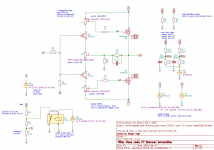
This is a first attempt to simulate the Pass Labs F7 amplifier by Nelson Pass.
The circuit diagram is taken from First Watt F7 review.
Resistor values have been estimated, a small Capacotor C1 has been added for frequency compensation. This simulation does not use the lateral power MOS devices, but the venerable complementary pair IRFP9240/IRFP240.
Some pictures and the simulation setup are attached. More info is available in F7readme.txt.
Attachments


Another update to the F5 V2 simulation
Attached you will find an update to the KiCad/Eeschema/ngspice simulation setup for the F5 Turbo V2 amplifier (designed by Nelson Pass).
The diode models for the MUR3020 diodes have been added. Still the diode models don't have self-heating with feedback. This will only be available in ngspice-33. So the diode temperature has been set to 50°C above ambient temperature.
Attachments

Installing ngspice is not the major hurdle to using open source simulators, especially, if a distribution provides ready compiled repositories and a package manager with automatic dependency resolution. The real NIGHTMARE is DECEIFERING how to use the open source graphical front end, and as if this was not enough of a hurdle, understanding or better learning how to input a schematic.
A member of these fora, very correctly wrote, open source applications are half baked applications, which worked for their developers with little to no attention to making them accessible to users in general.
A member of these fora, very correctly wrote, open source applications are half baked applications, which worked for their developers with little to no attention to making them accessible to users in general.
Off topic: I'm using open source (linux) successful for about 27 years since slackware 1.0 has been released (The Slackware Linux Project: Slackware Release Announcement)...
A member of these fora, very correctly wrote, open source applications are half baked applications, which worked for their developers with little to no attention to making them accessible to users in general.
I like the flexibility of those "half baked applications" - I see such software parts more like LEGO bricks ...
BR, Toni
Fun fact: SPICE2 was open source, free software, and released in 1975. Many subsequent commercial products sold by for-profit software companies, began with the free code that UC Berkeley gave away.
This was a decade before the Free Software Foundation was created by Stallman (1985), and also two decades before the Open Source Initiative was created by Raymond et al (1998).
This was a decade before the Free Software Foundation was created by Stallman (1985), and also two decades before the Open Source Initiative was created by Raymond et al (1998).
How to install KiCad/Eeschema/ngspice on Windows 10 to run the Pass Labs examples
A step-by-step approach
***** KiCAD/Eeschema *****
Download KiCad 64 bit release version from Windows | KiCad EDA
(about 1.200 GByte)
Current version is 5.1.6
Install KiCad to the standard path C:\Program Files\KiCad
ngspice-31 is included (libngspice-0.dll in C:\Program Files\KiCad\bin)
The schematic entry program is called Eeschema (Eeschema.exe in C:\Program Files\KiCad\bin)
*****
***** Replace ngspice-31 by ngspice-32 (to allow eletrothermal simulation and running the PassLab examples) *****
Download ngspice-32 dll from Download ngspice from SourceForge.net
Copy msys-ngspice-0.dll from ngspice-32_dll_64.zip\Spice64_dll\dll-mingw\ to C:\Program Files\KiCad\bin.
In C:\Program Files\KiCad\bin rename libngspice-0.dll to libngspice-0-orig.dll
In C:\Program Files\KiCad\bin rename msys-ngspice-0.dll to libngspice-0.dll
*****
***** Provide PSPICE compatibility *****
Create a new text file named spice.rc
The contents of the file shall be the next two lines:
* user-defined init file
set ngbehavior=ps
Place this file spice.rc into your HOME directory. This typically will be C:\Users\<your name>
*****
***** Download and install standard ngspice for special applications *****
This is not required to run the Passlab examples, but might be of interest because the Eeschema/ngspice standard interface is rather limited.
Download ngspice zip file fromDownload ngspice from SourceForge.net
Expand the zip file to C:\ directory. You will get C:\Spice64. ngspice.exe is in C:\Spice64\bin
*****
Example: Starting the F7 simulation
Install KiCad/ngspice as described above.
Download https://www.diyaudio.com/forums/att...e-opensource-simulator-passlabf7-diyaudio-zip and expand it to a directory of your choice, e.g. to D:\kicad-examples.
Start Eeschema by double click on C:\Program Files\KiCad\bin\Eeschema.exe.
File->Open->D:\kicad-examples\PassLabF7-diyaudio\F7thermal-1.sch -> Tools -> Simulator -> Run Simulation
Plotting after simulation has finished:
-> Add Signals -> V(Q5tj)
To run external ngspice with the embedded script (file script1.txt)
Start Eeschema by double click on C:\Program Files\KiCad\bin\Eeschema.exe.
File->Open->D:\kicad-examples\PassLabF7-diyaudio\F7thermal-1.sch -> Tools -> Generate Netlist File...-> Spice -> Default format -> Simulator Command: C:\Spice64\bin\ngspice.exe -> Run simulator
- Home
- Design & Build
- Software Tools
- Installing and using ngspice - an opensource simulator