I show the appearance here. Something I (or my Windows) is doing wrong.
Another topic:
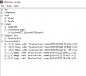
Would it be feasable to implement a feature somewhere in time that clear out the chart window (without clearing out the design task diagram window if it is running at the same time)? When you compare different solutions it would be great to start with an empty chart and just add on the few things that are in focus for the selected one. As it is now you have a lot of already used colours (Yes that can be chenged) but also a long list of rows that are not interesting. Clear list/chart now only exist while either load or show "everything". The asked for option would be "Clear list/chart".
Another topic:
Would it be feasable to implement a feature somewhere in time that clear out the chart window (without clearing out the design task diagram window if it is running at the same time)? When you compare different solutions it would be great to start with an empty chart and just add on the few things that are in focus for the selected one. As it is now you have a lot of already used colours (Yes that can be chenged) but also a long list of rows that are not interesting. Clear list/chart now only exist while either load or show "everything". The asked for option would be "Clear list/chart".
Attachments

Would it be feasable to implement a feature somewhere in time that clear out the chart window?
Click on the "Legend" panel with the right mouse button then choose "Remove All" from the context menu.
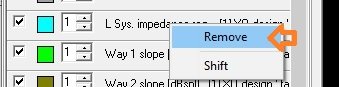
It's also possible to remove a single characteristic: right-click on a characteristic name inside the "Legend" panel and choose "Remove".
When you compare different solutions it would be great to start with an empty chart and just add on the few things that are in focus for the selected one.
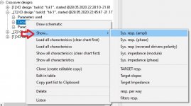
You can add characteristics one by one. From the "Circuits" context menu select "Show..." and you'll get a submenu where you can choose type of characteristic you want to display.
When I sat the offset to 2 cm I got an error that th FRD data is missing.
"FRD data is missing" is not an error it's a warning. When "create a new task" is chosen, XMachina prepares a list of Ways existing in the design file to make it available for selection in the design setup window. It is checked if all the Way nodes have relevant data loaded. If something is missing this warning appears. To make it disappear you have to load frd into the Way node. Or if you do not intend to use the uncompleted node you can safely ignore this warning.
I change it back to 0 - But the error message doesn´t go away. THe system think the value still is set to 2cm, even after closing and restarting.
The design file is autosaved just after starting design that's a possible reason why this delay value recovered after closing. But you should be able to change it after reopening.
I think that "missing FRD data" warning has nothing to do with "Delay" parameter issue, they came out together by coincidence.
Attachments

Click on the "Legend" panel with the right mouse button then choose "Remove All" from the context menu.
It's also possible to remove a single characteristic: right-click on a characteristic name inside the "Legend" panel and choose "Remove".
"FRD data is missing" is not an error it's a warning. When "create a new task" is chosen, XMachina prepares a list of Ways existing in the design file to make it available for selection in the design setup window. It is checked if all the Way nodes have relevant data loaded. If something is missing this warning appears. To make it disappear you have to load frd into the Way node. Or if you do not intend to use the uncompleted node you can safely ignore this warning.
The design file is autosaved just after starting design that's a possible reason why this delay value recovered after closing. But you should be able to change it after reopening.
I think that "missing FRD data" warning has nothing to do with "Delay" parameter issue, they came out together by coincidence.
Thanks for all the explanations. They are all great - Especially the ones with "remove"!!!! 🙂🙂🙂
XO slopes above output
I have once again run into some mysteries.
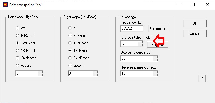
Now when I am setting the slopes for the XO they always land above the output. Regardless of how I set the XO set up. Tried even both plus or minus of the same dB value but it came out the same. What do I do wrong ?
I have once again run into some mysteries.
Now when I am setting the slopes for the XO they always land above the output. Regardless of how I set the XO set up. Tried even both plus or minus of the same dB value but it came out the same. What do I do wrong ?
Attachments

Left slope... is that the slope that slopes left or a slope to the left? 🙂 If only one slope?
Unconventional naming - seldom seen, if ever... maybe for a reason...
//
Unconventional naming - seldom seen, if ever... maybe for a reason...
//
Left slope... is that the slope that slopes left or a slope to the left? 🙂 If only one slope?
Unconventional naming - seldom seen, if ever... maybe for a reason...
//
I found that interesting too. As I figured it out it is the slope that is "sloping to the left", which mean the right slope (High pass). 😉
Maybe it´s and English expression that we sweedes doesn´t grasp. 🙂
Last edited:
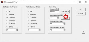
Check out "cross-point depth" parameter. It's -6dB by default so the slopes begin 6dB above the target, if it has positive value then slopes start below the target.
Ok,
But for me - (minus) mean lower. So -6dB is 6 dB lower than the output. But that´s just me 🙂
Also I did change to both plus and minus but couldn´t see a difference. Must have made something wrong apparently.
Left slope... is that the slope that slopes left or a slope to the left? 🙂
This is an "edit crosspoint" window, so the "left slope" is on the left side of the crosspoint and the "right slope" is on the right. I thought (mistakenly, as it turns out) naming it in that straightforward way makes everything look clearer.
Also I did change to both plus and minus but couldn´t see a difference. Must have made something wrong apparently.
After changing input parameters you have to start a new design to see any effects.
This is an "edit crosspoint" window, so the "left slope" is on the left side of the crosspoint and the "right slope" is on the right. I thought (mistakenly, as it turns out) naming it in that straightforward way makes everything look clearer.
Well you are right if we wright in this way:
The High pass slope (that belongs to the tweeter) of the filter is on the left (leaning left) side of xo position in a chart/diagram because it is there it should NOT let tweeter frequencies pass.
The Low pass slope (that belongs to the woofer) of the filter is on the right (leaning right) side of xo position in a chart/diagram because it is there it should NOT let woofer frequencies pass.
But I agree, it gets a little bit confusing in the Edit crosspoint window. In a chart/diagram the tweeter frequencies are to the right but in this menu they are handled to the left. Although the naming is correct in each part of the menu. Maybe just switch places of the two (in a 2-way) menu parts.
Last edited:
There is a small button with '?' at the corner of the crosspoint editor window. Press it to get quick sketchy reminding of what's what.But I agree, it gets a little bit confusing in the Edit crosspoint window.
Last edited:
Thanks for the software. It finally allowed me to muster courage to dwell into passive crossovers.
I have a question. Are there any readily available component lists that's correspond to what's available on Mouser and digikey etc.?
I have a question. Are there any readily available component lists that's correspond to what's available on Mouser and digikey etc.?
This shouldn't be very difficult to create such a list. For digikey, just save the search result as csv. then open this csv in a spreadsheet and delete unnecessary columns. For example, for coils the following columns should be kept: inductance and resistance. Optionally, you can keep the "price" column and several others that you want to be saved in the component description. Then use the "Load Inductor list" function in XMachina and do copy-paste from the spreadsheet. There may be some problems with Greek "micro" character or "Ohm" characters which are not recognized. But this can be easily corrected with the find and replace function. Just replace "Ohm" with "R" and Greek "micro" with "u"character.
Once the component list is created it can be shared with another projects as the component lists can be copy-pasted or saved-loaded.
And maybe a general remark. It is not worth making extremely long lists of components. This may not improve the possibility of achieving a better result but will certainly increase the combinatorial complexity of the task. As a result, the design process may slow down unnecessarily.
This shouldn't be very difficult to create such a list. For digikey, just save the search result as csv. then open this csv in a spreadsheet and delete unnecessary columns. For example, for coils the following columns should be kept: inductance and resistance. Optionally, you can keep the "price" column and several others that you want to be saved in the component description. Then use the "Load Inductor list" function in XMachina and do copy-paste from the spreadsheet. There may be some problems with Greek "micro" character or "Ohm" characters which are not recognized. But this can be easily corrected with the find and replace function. Just replace "Ohm" with "R" and Greek "micro" with "u"character.
Once the component list is created it can be shared with another projects as the component lists can be copy-pasted or saved-loaded.
And maybe a general remark. It is not worth making extremely long lists of components. This may not improve the possibility of achieving a better result but will certainly increase the combinatorial complexity of the task. As a result, the design process may slow down unnecessarily.
Thanks. I'll try it.
It seems just the poly capacitors alone run into 50 pages on Digikey. Could you please suggest criterion/parameters to narrow down the capacitor/resistor/inductor list to suit audio crossover purposes?
It seems just the poly capacitors alone run into 50 pages on Digikey. Could you please suggest criterion/parameters to narrow down the capacitor/resistor/inductor list to suit audio crossover purposes?
For initial testing and experimenting with XMachina I would suggest generating lists of components instead of loading them. Generating is much easier and faster than loading.
Here on the old video, R L and C lists generation is shown from 0:15 to 0:45.
FR ps220 circuit design with XMachina. - YouTube
The generator offers some standard ranges for R L C (which can be freely changed). Values of the elements are generated according to the standard series E12 or E24, so there should be no problem with availability of the components that will appear in the circuit.
Loading lists of components is particularly applicable for coils because the inductance values offered by manufacturers often do not coincide with the standard E12 / E24 values and coils may have a wide range of resistances. But when you want to start a design "to give a try", you can even skip loading the coil lists and use the component generator.
A special case where you cannot do without loading component lists is when you intend to use the "reduce circuit price" option in the task settings.
It seems just the poly capacitors alone run into 50 pages on Digikey. Could you please suggest criterion/parameters to narrow down the capacitor/resistor/inductor list to suit audio crossover purposes?
Yes, look at the list on Solen.ca .
- Home
- Design & Build
- Software Tools
- Automatic crossover designing with XMachina