Hi,
Just found this and got really interested. I am on a road trip with my wife w just an iPhone to read. Limited ability to read big documents......
I am about to build a 2 way tapered MLTL speaker. It will have four sections. A chamber behind the drivers, then a tapered part, a straight part and last a tapered with a port. Have some output graphs from MathCad (and possibly Hornresp). Could this output and the baffle size (and other measures) be used as input to this software for xo calculations?
All you need to start XMachiana is frequency and impedance characteristics of all ways in the system. It would be good to have them measured. But there is also an option to load (from outer source) simulated LF response and baffle diffraction characteristic and merge/overlay them with the characteristic provided by the manufacturer.
All you need to start XMachiana is frequency and impedance characteristics of all ways in the system. It would be good to have them measured. But there is also an option to load (from outer source) simulated LF response and baffle diffraction characteristic and merge/overlay them with the characteristic provided by the manufacturer.
What i will have is the manufactures graphs and Small thiele parameters of the two drivers (SB17NRX2C35 and Monacor DT-300 +WG), all kinds of output graphs from MathCad for the tapered MLTL i am intending to build, and baffel size (and the rest of the cabinet measures).
How long will that last for XMachina?
I have now downloaded "latest version" and the manual. When I start the Exe-file it starts but then nothing works. I cant do what is expected from me - create the component lists etc.
I do have a Windows 10 64bit environment. It says 32 bit in the manual - are there any 32 bits around these days?
I do have a Windows 10 64bit environment. It says 32 bit in the manual - are there any 32 bits around these days?
Last edited:
I have tried running XMachina under Win10/64, Win7/64, WinXP/32, no problems occurred. I suppose it should also work under Wine/Linux (or MacOS) but I haven't tried this yet.
Coming back to your case, can you see the application window or it doesn't start at all? If it starts, can you see the tree-view on the left panel of the application window? Can you expand/collapse tree-view nodes clicking "+" that are next to the nodes? For example when you expand the "Components" node and click with the right mouse button on "Cap. lists", are you getting something like on the picture attached?
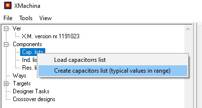
Coming back to your case, can you see the application window or it doesn't start at all? If it starts, can you see the tree-view on the left panel of the application window? Can you expand/collapse tree-view nodes clicking "+" that are next to the nodes? For example when you expand the "Components" node and click with the right mouse button on "Cap. lists", are you getting something like on the picture attached?
Attachments

I have tried running XMachina under Win10/64, Win7/64, WinXP/32, no problems occurred.Aare you getting something like on the picture attached?
Ok,
Reinstalled and now it works.
Are there any usable lists of components "out there" that you know of or do I just gererate one (which will not contain prices)? If there are lists it really doesnt matter if it is in the correct currency or even available here in Sweden as the price etc can be used for evaluation rather than buying.
What about the output from MathCad, can it be used in XMachina together with or instead of driver (woofer) specs?
FWIW
9 parts total, diffraction and box has not tried yet.
...correct as needed I am still learning Thanks!
Could you post your design file so I could have look.
Possible reasons for getting complicated solutions: very steep target filter slopes, strong correction on the spl characteristic, drivers are much out of phase near the cross-point, very strong reverse phase dip required, target spl above drivers spl, target impedance above drivers nominal impedance, values in the component lists do not cover defined cross-point frequencies, etc.
Sometimes a slight modification in the task settings can make a noticeable difference in the results.
9 parts total, diffraction and box has not tried yet.
...correct as needed I am still learning Thanks!
Attachments
All you need to start XMachiana is frequency and impedance characteristics of all ways in the system. It would be good to have them measured. But there is also an option to load (from outer source) simulated LF response and baffle diffraction characteristic and merge/overlay them with the characteristic provided by the manufacturer.
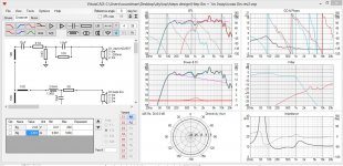
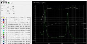
So what I did here is to import a SPL graph that is a combination of what is provided by the manufacturer and what is calculated for the wooferm and actual measures in another design for the tweeter. That is what is available. I haven´t seen any graphs from Monacor on their tweeter.
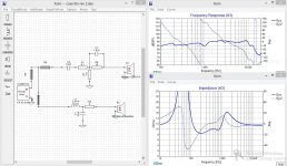
Got my first circuits. Fun! But they appeared as one diagram circuit for the tweeter and one for the woofer. then the component list below. Can I get them together in some way.
I am also looking for ready component lists. Must be some out there.
Thanks so far for a great software!!
Generating component lists is fast and easy and quite enough until you're experimenting and playing with XMachina not willing to implement any of the results.Ok,
Are there any usable lists of components "out there" that you know of or do I just gererate one (which will not contain prices)? If there are lists it really doesnt matter if it is in the correct currency or even available here in Sweden as the price etc can be used for evaluation rather than buying.
I see the following benefits of using defined component lists:
1) it's possible use real values of coil inductance and esr in the design which are often far from typical values.
2) There is an option of optimizing circuit price.
3) Entering reference numbers in the component descriptions makes placing order easy and fast.
2) There is an option of optimizing circuit price.
3) Entering reference numbers in the component descriptions makes placing order easy and fast.
Ok,
What about the output from MathCad, can it be used in XMachina together with or instead of driver (woofer) specs?
I don't know what you have in MathCad. If these are frequency characteristics and you're able to export them as a table with frequency/dBspl/phase format then probably yes. XMachina can also read characteristics from pictures so another possible way of communicating with MathLab would be making a screenshoot of a chart and pasting it into XMachina "Load from picture" window.
9 parts total, diffraction and box has not tried yet.
...correct as needed I am still learning Thanks!
it's great that there is a progress.
Creating a high pass slope of the cross-point bare in mind that this adds to the roll off slope of the tweeter resulting that filtering may be too soft for the situation. Your high pass filter is 6dB/oct electrically and crosover frequency is <1kHz. I would probably consider increasing the target high pass slope of the filter.
Generating component lists is fast and easy and quite enough
I understand that, and I atomatically created the lists with the software. Great for a start, but I was more interested in knowing if anyone has some lists of "real components". As I am not the first user of the software. 🙂
I created what I could get from design tool MathCad, previous design measures and manufacturers. Quite ok to start with.
The circuit comes ut as two different parts for the tweeter ande woofer. Is that on purpose, and can it be changed?
Difraction tool and Box tool doesn't do anything. Should they? 🙂
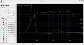
Some intersting results in the picture
Attachments
Suddenly only the top part of the progress window is showing. THe lower part is "gone" and i cant find or start it 🙂 🙂
So its a separate "standard display windows" just starting at the same time as the calculation process. I get it 😎😛Suddenly only the top part of the progress window is showing. THe lower part is "gone" and i cant find or start it 🙂 🙂
And now it´s gone again and there is no "Circuit" node in the Design task node for the ongoing design. So how do I then open the graphs that are constantly updated in the ongoing design task??????
The circuit comes ut as two different parts for the tweeter ande woofer. Is that on purpose, and can it be changed?
Just assume that the inputs are connected.
Difraction tool and Box tool doesn't do anything. Should they? 🙂
You can setup them to call external tools. It's in the environment settings. Quite a time ago when I was experimenting with simulated characteristics I had it configured to start execs of winisd (box tool) and edge (diffraction tool). The results were used via screenshots then "load from picture" window.
And now it´s gone again and there is no "Circuit" node in the Design task node for the ongoing design. So how do I then open the graphs that are constantly updated in the ongoing design task??????
the "circuits" sub-node appears after the design is finished. ongoing design characteristics are on the design chart window. if the window was closed you can reopen it choosing "options/show graphs" from the menu above the progress bar. It's possible to display characteristics of a finished design even if there is ongoing design. click with the right mouse button on the "circuits" node to see the options. The characteristics will appear in a separate window and won't mixup wit the characteristics of ongoing design.
if the window was closed you can reopen it choosing "options/show graphs" from the menu above the progress bar.
That was the problem. I did identify this Options/Open graph directly but it didn´t work. Nothing happened!
It means that your window wasn't probably closed but just minimized. To restore it press this:That was the problem. I did identify this Options/Open graph directly but it didn´t work. Nothing happened!
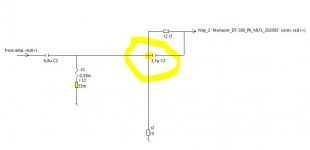
1) Is the yellow mark at the picture a connection point or just two wirings passing by each other?
There are no "floating wires" in XMachina. Any crossed wires should be considered as connected.
I was thinking of such feature but it wasn't eventually implemented. Possible reason is that crossover circuit is usually only a few parts and transferring it to any external tool takes a minute.2) Is it or will it be a way to export also the wiring diagram, and not only the list of material?
Attachments
It means that your window wasn't probably closed but just minimized. To restore it press this:

This "standard windows" feature to show the different active sessions for a specific application doesn´t show up. If it had I would have seen it. Just strange. Not now either, while running another design task. Well, it is what it is 🙂
Also interesting after about 10 different run (with different 16 schemas) on the exact same set-up, except for different settings for time, and some smaller differencies in steps/oct I have now 4 very good different suggestions. These are all very good in response, phase and impedance - but very different. Interersting tast to select 🙂
Attachments

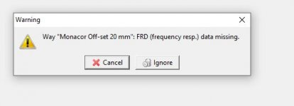
Offset value error
Once again I stumbled into a strange problem.
When I sat the offset to 2 cm I got an error that th FRD data is missing. Ok, then I change it back to 0 - But the error message doesn´t go away. THe system think the value still is set to 2cm, even after closing and restarting.
How do I to dissappear?
Once again I stumbled into a strange problem.
When I sat the offset to 2 cm I got an error that th FRD data is missing. Ok, then I change it back to 0 - But the error message doesn´t go away. THe system think the value still is set to 2cm, even after closing and restarting.
How do I to dissappear?
Attachments
- Home
- Design & Build
- Software Tools
- Automatic crossover designing with XMachina