Does anyone have a better answer than driving with a square wave and measuring the plot?
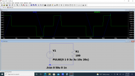
In any case, you may have run up against the initial conditions problem with pulse sources. Using two pulses in series makes a bipolar square wave with zero Volts at time zero. A finite rise time is required but should not be a problem.
As long as you know how to measure slew rate rather than rise time, there's nothing wrong with using a square wave.
Jan
For BJT input stage with no emitter degeneration resistors, an input square wave amplitude > 1.2V pk-pk will ensure slewing in almost all cases.
For BJT input stage with emitter degeneration resistors, an input square wave amplitude > 2.5V pk-pk will ensure slewing in almost all cases.
For JFET input stage, best to apply an input square wave amplitude > 3V pk-pk
Remember that output_pk_pk = gain * input_pk_pk . If you're testing a circuit whose closed loop gain is high (or whose output clipping levels are low), these tests could very possibly push the amplifier into clipping. So measure the slew rate from ~25% to ~75% on the scope, and disregard the clipping region.
You'll need a pretty fast square wave generator, with very small rise/fall times, because
- input_slew_rate >= output_slew_rate / gain
measuring slew rate
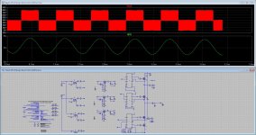
I found this here:
How to plot dy/dx versus x of a given y=f(x) plot in LTspice? - Electrical Engineering Stack Exchange
And I tried it out:
I did find that the maximum timestep has to be set small and there can be a auto-scale problem with the derivative.
I found this here:
How to plot dy/dx versus x of a given y=f(x) plot in LTspice? - Electrical Engineering Stack Exchange
And I tried it out:
I did find that the maximum timestep has to be set small and there can be a auto-scale problem with the derivative.
Attachments
Last edited:
I was quite good at simulating in LT Spice before I took a break. But now I'm very rusty. Also, I'm now using Windows 10. I have a large file of tube models, and I need to get them into LT Spice, but I cannot see where to put them. I put the symbols in with no trouble, but I cannot see where to put the large text file of tube models.
Last edited:
LTspice looks for models under the lib\sub folder. You can place your tube library file there.
But I created a User folder under lib\sub for all of my third party models and libraries. That keeps them separate from the built-in models. If you do this, you will need to include the User folder in the path name when you include these models in your schematics; or in LTspice XVII you can specify this folder in settings. See the "Sym & Lib Search Paths" tab. Right-click in the Library Search Path box and browse to the folder that contains your own third party models and libraries.
But I created a User folder under lib\sub for all of my third party models and libraries. That keeps them separate from the built-in models. If you do this, you will need to include the User folder in the path name when you include these models in your schematics; or in LTspice XVII you can specify this folder in settings. See the "Sym & Lib Search Paths" tab. Right-click in the Library Search Path box and browse to the folder that contains your own third party models and libraries.
Last edited:
LTspice looks for models under the lib\sub folder. You can place your tube library file there.
But I created a User folder under lib\sub for all of my third party models and libraries. That keeps them separate from the built-in models. If you do this, you will need to include the User folder in the path name when you include these models in your schematics; or in LTspice XVII you can specify this folder in settings. See the "Sym & Lib Search Paths" tab. Right-click in the Library Search Path box and browse to the folder that contains your own third party models and libraries.
Thanks for that, Ray. I think I've got the hang of it now. It's all coming back to me.
Hi all here.
A goof night for the ones who are still active now. The sleep disorder types of umans.
I have work the whole night getting something to work, it did work before.
Now I find that I get this after copy parts from a other schematic into the new one, I am quite convinced that this was the problem, I do copy sometimes parts of schematic for use into a new one, I see LTspice does ruin it and the schematic is not working anymore, it get mucho errors, the only way to let it work is redrawn.
Do you guys experinced this? Maybe I am the only one who do copy parts over to new schematics.
I have redrawn the whole schematic and I get now woring one who does what it has to do properly. so very strange. I did wanted to test a 2110 gate driver for multilevel, and it does nicely, after redrawn so the say.
regards
Attachments
How do I simulate an ideal BJT?
Since there is no forum section dedicated to "idealised components" and this question is about simulating an ideal BJT, I will post here, as this section is about solid state and BJTs are solid state.
If any moderator or administrator decides this thread should be deleted, I will not take offence. This question is completely theoretical, very few people are bothered to simulate an idealised BJT.
My LTSpice's simulation requires a power supply to power the ideal transistor. The current source should behave as an ideal current source provided there is enough voltage to power the transistor and to feed the load. My simulation lacks a power source.
Attachments


Moved to:
Installing and using LTspice IV (now including LTXVII). From beginner to advanced.
I think this is the best place to ask this.
As I found the solution, I am posting it here:
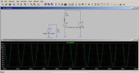
The solution is to assign to the current source's "Value" parameter the following conditional line:
I(R1) is the current through the input resistance. The statement is a condition which tells the current source to supply a current under condition the current is positive, that is, it is flowing in the right DC direction. The condition also amplifies the base current by 100 and produces a zero current when the input current flows in the opposite direction.
The solution is to assign to the current source's "Value" parameter the following conditional line:
Code:
I=if(I(R1)>0, 100*I(R1), 0)I(R1) is the current through the input resistance. The statement is a condition which tells the current source to supply a current under condition the current is positive, that is, it is flowing in the right DC direction. The condition also amplifies the base current by 100 and produces a zero current when the input current flows in the opposite direction.
Attachments
Last edited:
The constant current source is not properly set up to mimic the action of a BJT as the current cannot reverse direction. I tried several nested if statement but they did not work as planned. It seems there is a programmatic error (bug) in LTSpice. I tried several forms of nesting without success.
The statement goes like this:
Explanation:
If T is true, execute A, if T is untrue execute the last if statement. This is executed by first checking U for truth, if true B is executed, if false C is executed.
The statement goes like this:
Code:
if (T, A, if(U, B, C))If T is true, execute A, if T is untrue execute the last if statement. This is executed by first checking U for truth, if true B is executed, if false C is executed.
I would like to draw the attention of anyone interested in nested if statements that all my attempts failed on LTSpice. My advice is not to waste time, especially, if you are a student.
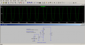
An ideal BJT may be constructed from two resistors and a current source. A resistor is used for the emitter-base junction and a current source with a parallel resistor is used to simulate transistor action. Obviously, the current source and its parallel resistor have to be programmed to behave like a transistor.
The programming is this:
I am attaching a screenshot.
An ideal BJT may be constructed from two resistors and a current source. A resistor is used for the emitter-base junction and a current source with a parallel resistor is used to simulate transistor action. Obviously, the current source and its parallel resistor have to be programmed to behave like a transistor.
The programming is this:
Code:
Value for R2:
R=if(I(R1)*100*10000<=12, 1G, 1n)

Value parameter for B1:
I=if(I(R1)>=0, 100*I(R1), 0)
I am attaching a screenshot.
Attachments
Last edited:
Little question about a simple TS391 I am trying to get to work in LTSpice.
Usually this is all straight forward, but I just get bogus results with an extremely simple comparator circuit.
I got the spice model from here;
Index of /Spice_Model_CD/Vendor List/STMicroelectronics/Standard Linear ICs/Spice
I also tried to model from ST's website;
TS391 - Low power, single voltage comparator - STMicroelectronics
As a symbol I just used the standard UniversalOpamp2 symbol and edit the pins to the one stated in the Spice file;
* 1 INVERTING INPUT
* 2 NON-INVERTING INPUT
* 3 OUTPUT
* 4 POSITIVE POWER SUPPLY
* 5 NEGATIVE POWER SUPPLY
.SUBCKT TS391 1 2 3 4 5
I am a little lost and confused, anyone a working model out there?
Ok, that was quick from myself.
This is rather silly from the SPICE model.
It only work on 5V (or lower), while the datasheet clearly says it can be used up to 36V.
Anyway to change this?
This is rather silly from the SPICE model.
It only work on 5V (or lower), while the datasheet clearly says it can be used up to 36V.
Anyway to change this?
I also tried to model from ST's website;
TS391 - Low power, single voltage comparator - STMicroelectronics
As a symbol I just used the standard UniversalOpamp2 symbol and edit the pins to the one stated in the Spice file;
* 1 INVERTING INPUT
* 2 NON-INVERTING INPUT
* 3 OUTPUT
* 4 POSITIVE POWER SUPPLY
* 5 NEGATIVE POWER SUPPLY
.SUBCKT TS391 1 2 3 4 5
The ST TS391 SPICE model uses the same pin order as the LTspice opamp2 symbol so you didn't need to edit either the model or the symbol's pin order. The model file appears to use node numbers instead of sequential numbers and this can be confusing, but it is the order that matters, not the actual numbers. The non-inverting input is pin 1, and the inverting input is pin 2. I think you have these reversed.
Don't change either the SPICE model file or the opamp2 symbol file and your simulation should work.
This list is from the spice model itself, I didn't change anything.
The standard opamp didn't work with it at all.
The standard opamp didn't work with it at all.
I'm not familiar with that chip so I can't comment on whether the model works or not. I was only offering an observation that the pin order in the model (see below) matches the pin order in the opamp2 symbol. The non-inverting input is listed first, followed by the inverting input. This is the opposite of what you show in your post #3073.
Sorry this wasn't helpful.
*-----------------------------------------------------------------------------------------
* TS391 spice macromodel
* CONNECTIONS : (corrected feb/17)
* 2 NON-INVERTING INPUT
* 1 INVERTING INPUT
* 44 POSITIVE POWER SUPPLY
* 55 NEGATIVE POWER SUPPLY
* 30 OUTPUT
*
**********************************************************
.SUBCKT TS391 2 1 44 55 30
Sorry if I missed this in a previous post. Is there an easy way to notch out a fundamental out of a waveform on a circuit output and display the distortion waveform in the same window as the output. I have tried adding the trace output-(input*gain) and I end up with a residual that is primarily the fundamental. I think I was pretty accurate with the settings and the circuit I am trying it on only has a couple of degrees of phase shift at mid band so not sure what went wrong or how to fix it.
Thanks
Marty
Thanks
Marty
Sorry if I missed this in a previous post. Is there an easy way to notch out a fundamental out of a waveform on a circuit output and display the distortion waveform in the same window as the output. I have tried adding the trace output-(input*gain) and I end up with a residual that is primarily the fundamental. I think I was pretty accurate with the settings and the circuit I am trying it on only has a couple of degrees of phase shift at mid band so not sure what went wrong or how to fix it.
Thanks
Marty
You mean in LTSpice?
I would just make a little notch circuit, with something like a LC
No idea if that can also be done with some kind of expression (probably it can)
- Home
- Design & Build
- Software Tools
- Installing and using LTspice IV (now including LTXVII), From beginner to advanced