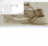
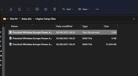
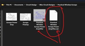
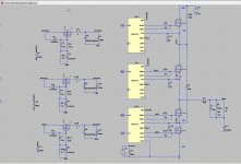
Here is the image blown up. I can see it is the Europa amp. Look where you have saved the files and see if you can see any .PLT files like these. PLT files will auto run the simulation.
I don't think there is anything wrong with the LT install from what I see.
My turn to watch TV... DCI Banks. Good luck, I'll look in tomorrow.
operator error 😀
Attachments
Then connect the VSS to ground with a 1 - 2 pF capacitor and a leakage resistance of 1 GigaOhm (Rpar=1G in capacitor parameters). You will not deny that there is always a capacitance between VSS and GND. Both for optocouplers and for transformers. That would help. I even made an element - a floating ground on such a principle. Give it a try. That should help.
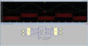
I did try, I get now close to what I want but only on the right side of the mosfet switches.
The left is a ordinairy sinusoidal signal and not switching so that is not good.
But it is more close.
regards
Attachments
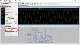
If you run a LT-XVII file in LT-IV
A schematic file created in LT-XVII should show as normal in LT-IV (assuming all the library models that are called are in LT-IV as well).
But when you run a schematic file created in LT-XVII it will show a black screen for the plots.
That's because the plot file is not backward compatible.
You need to re-create the plots you want, and then save them for LT-IV.
LT-IV plot files will open in LT-XVII.
operator error 😀
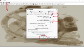
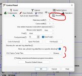
🙂 Have you set the following options up (attached) which delete .raw files when you close LT.
When you run a sim it creates lots of data and I like that to be cleared when I'm done. If you look in the location* LT stores these files you will see three files created while the sim is open and run.
*If you click 'Waveforms' you will see the location (I changed mine to somewhere else).
A .txt file is also created in the location the .asc is stored when the sim is run. That should disappear (self delete) when you close the sim.
Also (you probably will not do this) you can save the plot settings. If you click (to bring into focus) the plot pane and go to Plot Settings you have an option to store the .PLT file.
A schematic file created in LT-XVII should show as normal in LT-IV (assuming all the library models that are called are in LT-IV as well).
But when you run a schematic file created in LT-XVII it will show a black screen for the plots.
That's because the plot file is not backward compatible.
You need to re-create the plots you want, and then save them for LT-IV.
LT-IV plot files will open in LT-XVII.
Thanks Ian.
Poundy's files are ones I sent and some would probably have been created on LT IV although I have never seen black screen occur before.
Attachments
I did try, I get now close to what I want but only on the right side of the mosfet switches.
The left is a ordinairy sinusoidal signal and not switching so that is not good.
But it is more close.
regards
Simply put, you have a bad scheme. You have loaded the left transistors with high capacitance. I advise you to move this capacitor - put it after the inductance.
In today's Analog Dialog newsletter from Analog Devices (maintainer of LTspice):
"How to Use LTspice Simulations to Account for the Effect of Voltage Dependence
"Demand for smaller and smaller electronic devices .......calls for size constraints on components including multilayer ceramic capacitors (MLCCs). As a result, the effect of the voltage dependence (DC bias) is also being pushed into focus. In this article, we describe how to use LTspice® simulations to account for the effect of voltage dependence (or DC bias) caused by the use of ceramic capacitors with even smaller case sizes."
A MLCC cap can fall to half its rated value at just a few volts. This is not just poor bypassing, this is gross distortion of AC (audio) waves unless the cap is grossly oversize (which misses the usual reason to use MLCC).
Linear and TanH approximations are presented in LTspice syntax.
RAQ Issue 192: How to Use LTspice Simulations to Account for the Effect of Voltage Dependence | Analog Devices
https://www.analog.com/media/en/analog-dialogue/raqs/raq-issue-192.pdf
Attachments
Last edited:
what do the initial voltage drops represent here?🙂 Have you set the following options up (attached) which delete .raw files when you close LT.
When you run a sim it creates lots of data and I like that to be cleared when I'm done. If you look in the location* LT stores these files you will see three files created while the sim is open and run.
*If you click 'Waveforms' you will see the location (I changed mine to somewhere else).
A .txt file is also created in the location the .asc is stored when the sim is run. That should disappear (self delete) when you close the sim.
Also (you probably will not do this) you can save the plot settings. If you click (to bring into focus) the plot pane and go to Plot Settings you have an option to store the .PLT file.
Thanks Ian.
Poundy's files are ones I sent and some would probably have been created on LT IV although I have never seen black screen occur before.
Attachments
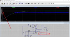
They are the DC voltages the circuit generates when powered by voltage source V2.
V2 is a constant DC source (like a battery). The other two voltage sources are dynamic (AC voltages) and the so circuit can not use these in generating the DC voltage levels.
The simulation calculates the DC conditions at what might called T=0 or time zero. If a voltage source appears after that time then it is discounted in the initial conditions.
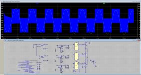
This shows the sim with V2 as a dynamic source appearing after just 0.1 seconds. So the initial conditions are now all 0V. In other words when the circuit is switched on there is no voltage anywhere.
The red trace is now the supply.
V2 is a constant DC source (like a battery). The other two voltage sources are dynamic (AC voltages) and the so circuit can not use these in generating the DC voltage levels.
The simulation calculates the DC conditions at what might called T=0 or time zero. If a voltage source appears after that time then it is discounted in the initial conditions.
This shows the sim with V2 as a dynamic source appearing after just 0.1 seconds. So the initial conditions are now all 0V. In other words when the circuit is switched on there is no voltage anywhere.
The red trace is now the supply.
Attachments
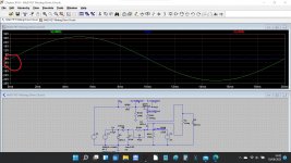
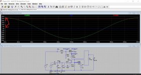
They are voltages the whole circuit needs in order to work as intended. You can call them 'inputs' if you wish.
V1 represents the AC voltage feed from the mains transformer. As soon as the real amp is turned on this voltage appears, however in the simulation the voltage at switch on is zero because the sine wave starts at zero. The simulation is all mathematically defined.
V3 represents the audio signal.
These are the three voltage at the instant of switch on. V1 and V3 are at zero when T=0
We could add a 90 degree phase shift to these so they start at the peak voltage which is 90 degrees or one quarter of the way through the cycle. If we made it 270 degrees it would start at the negative peak.
Attachments
Hi All
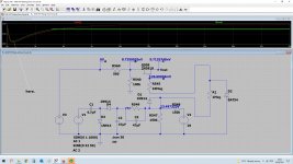
I have found after help from a Gan manufacturer how it is done with the flying cap buck. I was close all the way but did not see it, the need of separate drivers, so she use just High side of the gate driver for the above mosfets, and so I have level shifted the right way, have to say, it looks strange.
Only I need a way to get flying capacitor C2 to his working voltage without to wait very long when simulating, can I make a setup with C2 so it is on the desired charged voltage so I can see how it does?.
thanks.
Attachments
Last edited:
Kees you can set the node voltages to anything you like at simulation start.
It is something like .ic Vx=12V Vy=6V, check in the help file, initial conditions.
Edit:
.IC -- Set Initial Conditions
The .ic directive allows initial conditions for transient analysis to be specified. Node voltages and inductor currents may be specified. A DC solution is performed using the initial conditions as constraints. Note that although inductors are normally treated as short circuits in the DC solution in other SPICE programs, if an initial current is specified, they are treated as infinite-impedance current sources in LTspice.
Syntax: .ic [V(<n1>)=<voltage>] [I(<inductor>)=<current>]
Example: .ic V(in)=2 V(out)=5 V(vc)=1.8 I(L1)=300m
Use Initial Conditions. Normally, a DC operating point analysis is performed before starting the transient analysis. This directive suppresses this initialization. The initial conditions of some circuit elements can be can be specified on an instance-per-instance basis. Uic is not a particularly recommended feature of SPICE. Skipping the DC operating point analysis leads to a nonphysical initial condition. For example, consider a voltage source connected in parallel to a capacitance. The node voltage is taken as zero if not specified. Then, in the first time step, an infinite current is required to charge the capacitor. The simulator cannot find a short enough time step to make the current nonsingular, and a "time step too small convergence fail" message is issued.
With questions like this, the help file is really useful.
Jan
Last edited:
1. I place the following batch file in %userprofile%\AppData\Roaming\MicroSoft\Windows\Sendto
(posting adds a space in Sendto you have to remove)
%~d1
cd %1
del /S *.raw *.log *.fft
pause
I call it Spice cleaner.bat. You just right click the folder you used and sendto it to this batch file. You can wait and do a whole tree later.
2. I noticed yesterday that I could copy and past between schematics. Is this new?
Last edited:
2. I noticed yesterday that I could copy and past between schematics. Is this new?
I think you could do that all the way back to LTIV
Post #3007
Installing and using LTspice IV (now including LTXVII). From beginner to advanced.
Jan,
You are asking for an output current smaller than the listed minimum output current of 400 uA. Ask for more output current, and you should see the circuit work well.
Please refer to graph on top left corner of page 6 of the data sheet.
You are asking for an output current smaller than the listed minimum output current of 400 uA. Ask for more output current, and you should see the circuit work well.
Please refer to graph on top left corner of page 6 of the data sheet.
Hi
Am looking for a SPST NC relay in LT SPICE ( latest release )
Any ideas about where to find one ?
Many thanks
Am looking for a SPST NC relay in LT SPICE ( latest release )
Any ideas about where to find one ?
Many thanks
square waves
Does anyone have a better answer than driving with a square wave and measuring the plot?
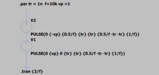
In any case, you may have run up against the initial conditions problem with pulse sources. Using two pulses in series makes a bipolar square wave with zero Volts at time zero. A finite rise time is required but should not be a problem.
how to measure slew rate?
Does anyone have a better answer than driving with a square wave and measuring the plot?
In any case, you may have run up against the initial conditions problem with pulse sources. Using two pulses in series makes a bipolar square wave with zero Volts at time zero. A finite rise time is required but should not be a problem.
Attachments
Hi
Am looking for a SPST NC relay in LT SPICE ( latest release )
Any ideas about where to find one ?
Many thanks
I found this:
LTspice: Voltage Controlled Switches | Analog Devices
but you may need to add features of real relays like coil inductance and resistance, contact bounce, etc. Be sure you understand the dangers of driving an inductance and the need for a fly-back diode.
- Home
- Design & Build
- Software Tools
- Installing and using LTspice IV (now including LTXVII), From beginner to advanced