I'm glad to help, and I hope that one of these symbols will work for you.
One note on the alternate symbol: The unlabeled pins show as rectangles inside the box and these cannot be removed from the symbol or else LTspice will report a pin mismatch between the symbol and the subcircuit. This is because the subcircuit contains 12 definitions in its pin order so the symbol must also have 12 pins, in the same order, whether they all have visible labels or not.
Good luck.
I had also did make a other part, also a lmg but this time a 1210.
These did give a error. Yours do fine Thanks. Now I now also how to automate the part, just load the lib and richt mouse click.
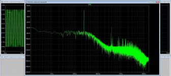
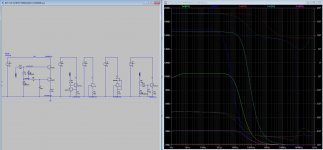
Here the sim, this is a open loop test, Gan is promissing stuf, very fast.
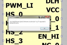
The other pic you see what the error is, do not see the pin NC_17 into lib by the way.
Attachments
Last edited:
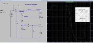
I made this circuit but now I am reading the ccs load resistor impedance (2kohm).
That seems about right. In theory, you would measure the 2k in parallel with the collector impedance which is much higher.
Do a .tran and look at the collector signal, to make sure the test current is a nice sine and the stage is not clipping.
Jan
Can you post the subcircuit file you are using for the LMG1210?
Yes is this one. but is this a subcircuit? I have only the .lib like the other one, who work very good so far.
regards
Attachments
What kind of circuit is this supposed to be, how will you use it? Can you show the actual application it will be used in, probably then it can be determined how to realistically test it. The way it is now you really test a single transistor because the whole biasing stuff is excluded from the test.
Jan
Jan
Yes is this one. but is this a subcircuit? I have only the .lib like the other one, who work very good so far.
This is a "library" file containing a number of subcircuits, most of which have specialized purposes. The one that is relevant is the very first one in the file, labeled ".SUBCKT LMG1210." This is a rather complicated model, with 21 "pins," and like the LMG1205 model, some of these pins are duplicates that are connected together internally. In the physical pin-out diagram on page 3 of the datasheet (see link below), there are 3 pins plus a pad labeled HS, 4 pins labeled NC or NC1 (for no connection), and 2 pins plus a pad labeled VSS. So you could create a symbol that consolidates these duplicate pins into one each (and ignore the NC pins) so that you have a symbol that looks like the one shown in section 8.2 on page 16 of the datasheet, which has only 12 identified pins. This is what I did for the LMG1205 "alternate" symbol. Give this a try and see if you can make that work; it will be a good learning experience!
https://www.ti.com/lit/gpn/lmg1210
V2 is separated from V2 otherwise the impedance reading is much lower...
That actually shows that the circuit has a low impedance and is not a good current source (if that is what it is supposed to be). The measurement doesn't lie ;-)
JKan
BTW, you could combine V1 & V2 in one source, they both have 55V DC.
Jan
He cannot, because only one of them can has the "AC 1" stimulus. He seems to be on the right track now with his impedance measurements.
It looks like he is measuring the output impedance of a current source, in a roundabout way.
If he used a single 55V voltage source, he would need a separate voltage source to provide the AC component in series with his current source output, but not in series with the bias leg on the left.
If he used a single 55V voltage source, he would need a separate voltage source to provide the AC component in series with his current source output, but not in series with the bias leg on the left.
He cannot, because only one of them can has the "AC 1" stimulus. He seems to be on the right track now with his impedance measurements.
Correct... the bias circuit for the cascode device should remain frozen.. stable... and can not be modulated by the measuring ac sweep.
I am comparing the output impedances of several different ccs for my most recent power amp.
RC,
It seems to me that you could delete R1 and R2 and simply read the current source impedance as 1/I(V1), given that you are providing an AC 1 stimulus.
Simple procedure: mimic the output voltage of your current source with the DC value of V1. V1 also has AC 1. Impedance = 1/I(V1).
Don't worry about the loudspeaker impedance measurement technique in post #2606.
Thank you so much.
Yours is the best solution.
Now I can clearly see the differences in impedance between the several ccs.
Do not mind me using the loudspeaker tech for my approach as I have been working as a loudspeaker designer for the last 4 years and so my mind is biased.
Yours is the best solution.
Now I can clearly see the differences in impedance between the several ccs.
Do not mind me using the loudspeaker tech for my approach as I have been working as a loudspeaker designer for the last 4 years and so my mind is biased.
Hi JanWhat kind of circuit is this supposed to be, how will you use it? Can you show the actual application it will be used in, probably then it can be determined how to realistically test it. The way it is now you really test a single transistor because the whole biasing stuff is excluded from the test.
Jan
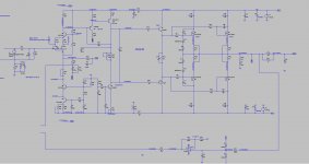
Here is the amp I am working on.
I am using a cascoded ccs for the IPS and a single bjt ccs for the VAS.
I need to determine the best value for R8 (vas ccs base stopper / RC filter) as it seems I can change THD distribution just by changing this resistor.
With R8 set to 1kohm, 3rd disappears.
Attachments
- Home
- Design & Build
- Software Tools
- Installing and using LTspice IV (now including LTXVII), From beginner to advanced