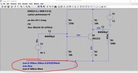
This (the images) is your file 'as is' with nothing changed at all.
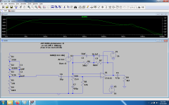
I think I can see one point of confusion that I haven't explained (or it was an error). So in post #19 I say '20 cycles' and that is therefore a time of 20* (1/4000) which is 5 milliseconds. To look at 5 milliseconds of data you would need to set the sim to say start at 240ms and end at 245ms. If we divide 5ms by 262144 we get 0.000000019073486328125 seconds.
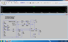
I see in post #19 I have 20ms as the time the data is plotted. So I'm going to run your file with 240ms and 245ms as the limits and retaining that same timestep. Thats the second image.
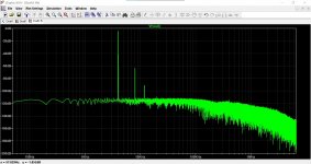
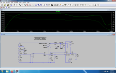
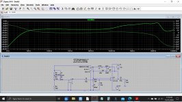
Going back to 20 milliseconds again and we get 0.020/262144 which is 0.0762939453125uS. Lets pop those numbers in. This is image 3.
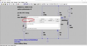
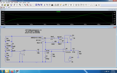
The last image is follows on and now has the transistor swapped for a 2N2222
I have attached the .asc so if you run it you should see exactly the same.
Does that help or not 🙂
I think I can see one point of confusion that I haven't explained (or it was an error). So in post #19 I say '20 cycles' and that is therefore a time of 20* (1/4000) which is 5 milliseconds. To look at 5 milliseconds of data you would need to set the sim to say start at 240ms and end at 245ms. If we divide 5ms by 262144 we get 0.000000019073486328125 seconds.
I see in post #19 I have 20ms as the time the data is plotted. So I'm going to run your file with 240ms and 245ms as the limits and retaining that same timestep. Thats the second image.
Going back to 20 milliseconds again and we get 0.020/262144 which is 0.0762939453125uS. Lets pop those numbers in. This is image 3.
The last image is follows on and now has the transistor swapped for a 2N2222
I have attached the .asc so if you run it you should see exactly the same.
Does that help or not 🙂
Attachments
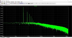


Yep that helps - these are more or less the pictures I am getting. The harmonics are all visible. It's just that the detail between the harmonics looks different in your original graphs from 2014 in #19. Perhaps that does not matter at all*, since the THD is the same.
Regarding maximum timestep: so basically this is to match the # of data points in the simulation to the 'data point samples' number of the FFT, right? E.g. 10ms by 262144 data points = record a data point every 0,0381..us, so you end up with a set of exactly 262144, correct? Just wondering, b/c this is something LTSpice could calculate on it's own.
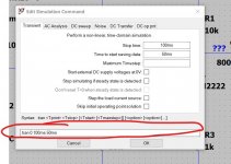
PS: if anyone follows the tutorial with LTSPICEXVII: seems there is a bug when you open "Edit Simulation Command" that the previous settings for this command disappaer or are filled with the settings of the last active command, and you have to re-enter them. Does not happen in IV
*am wondering if the detail between the harmonics, and the slope below -160dB is an artifact produced by the simulation only (e.g. rounding errors)
Regarding maximum timestep: so basically this is to match the # of data points in the simulation to the 'data point samples' number of the FFT, right? E.g. 10ms by 262144 data points = record a data point every 0,0381..us, so you end up with a set of exactly 262144, correct? Just wondering, b/c this is something LTSpice could calculate on it's own.
PS: if anyone follows the tutorial with LTSPICEXVII: seems there is a bug when you open "Edit Simulation Command" that the previous settings for this command disappaer or are filled with the settings of the last active command, and you have to re-enter them. Does not happen in IV
*am wondering if the detail between the harmonics, and the slope below -160dB is an artifact produced by the simulation only (e.g. rounding errors)
Last edited:
Yes, another good way. We now have seen three of four ways to import external models so there should be something to any bodies taste!
Can I change the subject? I am looking for a standalone version for Intusoft's Spicemod program. It is a spreadsheet-based app where you can enter all kinds of component datasheet parameters and it then builds a model for you.
It is part of the Intusoft environment but apparently it is also available stand alone; in fact the name is spicemode.exe .
But I can't find it. Anybody has it and/or experience with it?
Jan
From Intusoft:
SpiceMod is priced at $600 a copy.
ModelBuilder plus is priced at $1000 a copy.
Gives you another view on the incredible value of a free LTspice!
Jan
Last edited:
PS: if anyone follows the tutorial with LTSPICEXVII: seems there is a bug when you open "Edit Simulation Command" that the previous settings for this command disappaer or are filled with the settings of the last active command, and you have to re-enter them. Does not happen in IV
We all wondered what was going on with that one... Mike Engelhardt said it made life easier but didn't explain how... but once you get it 😉 then it very good.
It allows you to set up multiple commands on the sim.
Look at this. If you right click the .tran command at the bottom in that is in black and then click 'cancel' this box appears. Now change the directive from a 'Spice directive' to a 'Comment'. It changes to blue and becomes non active. Make the one you want to run a Directive rather than a comment.
So you can set many commands up at once. You can enter commands directly into the command line as well once you know and get used to the syntax and structure. So its pretty good.
Attachments
Have a read at post #1487
Installing and using LTspice IV (now including LTXVII). From beginner to advanced.
Installing and using LTspice IV (now including LTXVII). From beginner to advanced.
Ok, that works, thanks 😉
#1489: "The really weird part is that it may load part of an existing command, but scrambled." -> that threw me off
Am at #32, way to go
#1489: "The really weird part is that it may load part of an existing command, but scrambled." -> that threw me off
Am at #32, way to go
Last edited:
 that's good.
Because someone asked 🙂
This is the Blameless Class B set up for 1kHz and 20kHz along with the models needed.
You will have to alter the .include statement on the sim to include the models for your PC. If you keep the file name the same then change it to .include Cordell Models.txt
and keep the file and the .asc in the same folder or location.
I have large model file at the root of the C drive hence the include statement on the .asc
Attachments
Yesterday I did the most stupid thing i could and i updated my 2 years old version of LtSpice and every single design i built and it's totally reliable in the last 2 years shows tons of 10...12mhz ringing while in the old sims and the actual circuits there's no sign of instability. so according to the new LtSpice nothing works...Some phono preamps also show +5...8 db more highs in the 10...20khz region with a very well known commercial design that works for decades no matter what model of op-amp i use. Is it only me having this problem?
It seems like it is just you at the moment 🙂
Pick a sim with an obvious error such as the one you say has an 5 to 8db rise in the response and then troubleshoot that as if it were a real design and see why the response is incorrect.
No guarantees but if you post the .asc of that example someone may spot something.
Pick a sim with an obvious error such as the one you say has an 5 to 8db rise in the response and then troubleshoot that as if it were a real design and see why the response is incorrect.
No guarantees but if you post the .asc of that example someone may spot something.
... shows tons of 10...12mhz ringing
That's very odd. Or did you mean MHz?
Jan
@Jan.Sorry, yes, MegHz.
@Molly here's a very simple phono i built already in three different variations , but this is basically a famous phono schematic found in countless datasheet and real audio preamps .Changing op-amp changes the ringing point, but it doesn't cancel it. Changing schematics i get the same thing all over the place.i even ave some sims of some 0.1db riaa phono that are way out of specs...every single schematic i have now is ringing or have much higher highs or much lower bass.With entire sets of convergence rules i get the same thing...
@Molly here's a very simple phono i built already in three different variations , but this is basically a famous phono schematic found in countless datasheet and real audio preamps .Changing op-amp changes the ringing point, but it doesn't cancel it. Changing schematics i get the same thing all over the place.i even ave some sims of some 0.1db riaa phono that are way out of specs...every single schematic i have now is ringing or have much higher highs or much lower bass.With entire sets of convergence rules i get the same thing...
Attachments
There is nothing wrong with your LTSpice.
Start by using a decent Anti Riaa network.
Eliminating the top 1910R and the 536R below will give a proper Anti Riaa response.
Hans
Start by using a decent Anti Riaa network.
Eliminating the top 1910R and the 536R below will give a proper Anti Riaa response.
Hans
I used that anti riaa network in real circuits a few years ago on a phono preamp that was able to reproduce pretty good square waves up to 25khz and was linear with sine signals up to 480khz...i wouldn't blame that riaa as i used it since 2013...and the vdvs give pretty much the same result without inserting a cart there...
If it's nothing wrong with my new LtSpice then it means that the previous two years old edition was wrong and i can't really believe that.As long as i have a bunch of circuits that were built and work very well based on the older models, nothing can make me believe there's nothing wrong with the new edition.I didn't have that kind of response with any op-amp before yesterday for at least 2 years.
I used that anti riaa network in real circuits a few years ago on a phono preamp that was able to reproduce pretty good square waves up to 25khz and was linear with sine signals up to 480khz...i wouldn't blame that riaa as i used it since 2013...and the vdvs give pretty much the same result without inserting a cart there...
O.K. you know better, succes.
Hans
even if i modify the gain to 60db as for the MC cart...that resistor is part of a divider for mc cart signal.There is nothing wrong with your LTSpice.
Start by using a decent Anti Riaa network.
Eliminating the top 1910R and the 536R below will give a proper Anti Riaa response.
Hans
Attachments

Second mistake that you make, R10 is part if the Riaa network.
Changing its value, changes the FR.
Hans
Changing its value, changes the FR.
Hans
@Molly here's a very simple phono i built already in three different variations , but this is basically a famous phono schematic found in countless datasheet and real audio preamps................
Thanks 🙂
I can see you've had a lot of useful replies...
Although I don't dabble in RIAA circuits I can't really see an issue here. The opamp output is fine up to and beyond the audio band but then it will all fall to pieces because you are running the opamp at effectively unity gain once you get up to a couple hundred kHz. The opamp model may not even be that good at those extremes. You really need a band limited input signal I suspect.
Here is an inverse RIAA network I used together with feedback values from the LM4562 data sheet.
Attachments
@Hans
It's not my second mistake, apparently it was an unvoluntary riddle for yours. I did no mistake.You did one, a very big one as R5 in the antiriaa network is the one that give most of the gain for mm cart...I'm not going to load mm carts with 4.7 Kohms instead of 47 kohm just to have to have better reponse on paper ...No phono manufacturer give the riaa response with a real cart or a simulation of the real cart, they only use the antiriaa filter loaded with the recommended resistor only .
@Molly
here's a new simulation of te same circuit you have in the first post ,just different plot, and that tells me same thing i am seeing for 5 years on 3 different laptops and about 3 or 4 LtSpice versions , that LtSpice calculations are a bit random...
Attachments
- Home
- Design & Build
- Software Tools
- Installing and using LTspice IV (now including LTXVII), From beginner to advanced