@Mooly
Karl, there's some discussion on how to make your own spice symbols and models in the Superreg thread, that probably would be better placed in this thread. It starts from about post # 2103.
Can you take a look and move those posts if you think it is worthwhile?
Jan
Karl, there's some discussion on how to make your own spice symbols and models in the Superreg thread, that probably would be better placed in this thread. It starts from about post # 2103.
Can you take a look and move those posts if you think it is worthwhile?
Jan
Thanks Jan, those posts do seem unrelated to the diyAudio store thread. Lets see how they look over here 🙂
After several discussions how to get an op-amp in your design that's not part of the standard LTspice library, one possibility is to Auto Generate a symbol or .ASY file.
There is however an alternative way to get the job done, that's the route that I use to take.
Take for instance the OPA1611.
The spice model, in this case called OPA1611.Lib can be downloaded from TI as a zipped file.
After unzipping, place the .lib file in the directory where you want to build or already have your LTspice simulation circuit.
Let's say this directory is C:\Program Files\LTC\LTspiceXVII\NewFolder and a (test) circuit already made in this directory is called Op-Amp.asc.
The only thing still missing to test our OPA1611 is an .asy file.
First inspect the OPA1611.lib file by clicking on it to find the line with
.subckt OPA1611 IN+ IN- VCC VEE OUT
This tells you in what order the pins on the .asy file should be placed.
Close this .lib file and continue within LTspice with "File - New Symbol".
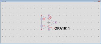
Now draw the triangle symbol of an op-amp, 4 points high and 4 points wide, but it could be anything else because the shape is unimportant but just convenient to keep it the same as the available LTspice models for ease of interchanging op-amps.
Place in the same order the 5 pins to the drawing, again similar to how LTspice uses to present their standard op-amps.
Once you have made such a model, you can reuse it as often as you like for other op-amps by renaming this .asy file, so you only have to do this once.
What you have made now should look like the first image below after having saved it as OPA1611.asc in the same \NewFolder directory as your .lib and your .asc files.
You still have to edit the attributes and tell where the .asy should get its information.
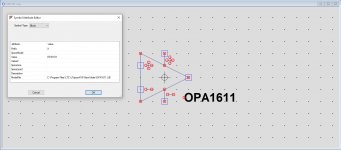
So still within the .asy file, click resp. "Edit - Atributes - Edit Attributes" and the following window will pop up, see second image below.
See to it that you fill in the all the things like here including the correct link to your .lib file and save the .asy file
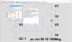
Reopen your Op-Amp.asc file and insert the OPA1611 by going to the Component selection symbol and resp. select New folder in the top line and the OPA1611, see third image.
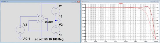
After having selected the OPA1611, place it in your model and run the sim, see fourth image.
When at a later stage you want to use the OPA1611 in another directory, you will have to copy the .asy file to that directory.
Hans
There is however an alternative way to get the job done, that's the route that I use to take.
Take for instance the OPA1611.
The spice model, in this case called OPA1611.Lib can be downloaded from TI as a zipped file.
After unzipping, place the .lib file in the directory where you want to build or already have your LTspice simulation circuit.
Let's say this directory is C:\Program Files\LTC\LTspiceXVII\NewFolder and a (test) circuit already made in this directory is called Op-Amp.asc.
The only thing still missing to test our OPA1611 is an .asy file.
First inspect the OPA1611.lib file by clicking on it to find the line with
.subckt OPA1611 IN+ IN- VCC VEE OUT
This tells you in what order the pins on the .asy file should be placed.
Close this .lib file and continue within LTspice with "File - New Symbol".
Now draw the triangle symbol of an op-amp, 4 points high and 4 points wide, but it could be anything else because the shape is unimportant but just convenient to keep it the same as the available LTspice models for ease of interchanging op-amps.
Place in the same order the 5 pins to the drawing, again similar to how LTspice uses to present their standard op-amps.
Once you have made such a model, you can reuse it as often as you like for other op-amps by renaming this .asy file, so you only have to do this once.
What you have made now should look like the first image below after having saved it as OPA1611.asc in the same \NewFolder directory as your .lib and your .asc files.
You still have to edit the attributes and tell where the .asy should get its information.
So still within the .asy file, click resp. "Edit - Atributes - Edit Attributes" and the following window will pop up, see second image below.
See to it that you fill in the all the things like here including the correct link to your .lib file and save the .asy file
Reopen your Op-Amp.asc file and insert the OPA1611 by going to the Component selection symbol and resp. select New folder in the top line and the OPA1611, see third image.
After having selected the OPA1611, place it in your model and run the sim, see fourth image.
When at a later stage you want to use the OPA1611 in another directory, you will have to copy the .asy file to that directory.
Hans
Attachments
Yes, another good way. We now have seen three of four ways to import external models so there should be something to any bodies taste!
Can I change the subject? I am looking for a standalone version for Intusoft's Spicemod program. It is a spreadsheet-based app where you can enter all kinds of component datasheet parameters and it then builds a model for you.
It is part of the Intusoft environment but apparently it is also available stand alone; in fact the name is spicemode.exe .
But I can't find it. Anybody has it and/or experience with it?
Jan
So still within the .asy file, click resp. "Edit - Atributes - Edit Attributes" and the following window will pop up, see second image below.
See to it that you fill in the all the things like here including the correct link to your .lib file and save the .asy file
This seems to be the key question in my failing to get the model I want.
Within which .asy file are you talking about? You didn't show how to create the .asy file yet.
It's probably obvious to everybody, but it's not for me. I feel I'm so close and just losing a detail I'm not paying attention to.
Yes.
Jan
Sorry to say Carlos, but it’s all in my posting.
You want to run a Marathon but you did not prepare yourself at all, that’s why you miss most important points.
Hans
You want to run a Marathon but you did not prepare yourself at all, that’s why you miss most important points.
Hans
I'm having a problem right now that could easily be solved by running AC analysis based on final transient operating points and would like to know if that option is available in LTSpice. I use it all the time in Spectre, but can't seem to find how to use it here... does it exist?
LTspice has options .savebias and .loadbias, which save and re-load DC operating points.
Not sure that is what you want though.
The Help explains details.
Jan
Not sure that is what you want though.
The Help explains details.
Jan
LTspice has options .savebias and .loadbias, which save and re-load DC operating points.
Not sure that is what you want though.
The Help explains details.
Jan
Jan,
Thanks so much for the quick reply. This is exactly what I was looking for. It's not as seamless, but it works great!
You mentioned Spectre. I believe it is an RF simulator, right? I remember getting a demo version long time ago, maybe 20 years?
The author was the developer of Isspice I believe. Memories.
Jan
The author was the developer of Isspice I believe. Memories.
Jan
Looks like both images in post 16 are showing the response for the 2N3055 when the first one was meant to be for the 2N2222. So well spotted 🙂
Right. Thanks 🙂
@Mooly
cannot replicate the FFT graphs under #19 with either transistor. Are you sure u really used 2N3055 or 2N2222 ? The pictures are too small to check, but the text label seems something else.
BR
PS: the same file produces different graphs on LTSpice IV vs. XVII also. But still not the same like in #19. I want to confirm first the transistor used. Other parameters should be identical.
Last edited:
Furthermore, the shape of the FFT graphs seems to depend highly on what is put in as timestep, plus the precision of that number.
If I put in the exact timestep for the 10ms run (0.03814697265625us) I'm back to the first simple FFT graph. This is confusing me.
The result for THD is almost correct (lest the last 3 digits): 0.744286%
EDIT: with 100ms/90ms (stop time/t.t.start) the THD is 0.744373%, so this is a matter of stabilizing.
BR
Last edited:
I'm just running the file downloaded from post #14.
The input voltage on that file is set to just 10 cycles and so that needs clearing (deleting) for a longer sim run. Also have you set the input to 4kHz to match the timestep of 0.0190734uS in post 19?
Also have you got the command of .option plotwinsize=0 on the sim?
I'll take a closer look later if you are still having problems. It was all a long time ago now 🙂
Thanks for taking the time, I know it was long ago 🙂
Yes, I had set to 1000 cycl and also tried clearing it. .option plotwinsize=0 is there, too.
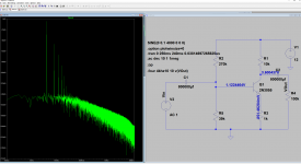
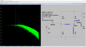
Here are pictures of both 10ms run and 20ms run. I'll also attach my file, if you have the time, perhaps you could just run it.
Btw, how does that work? For 10ms you calculate 10ms/262144 = 0.0381469us, ok.
But previously, it was 20ms (230ms-250ms), not 20 cycles (5ms@4kHz), so should it be 20ms/262144 = 0.0762938us instead?
BR
Yes, I had set to 1000 cycl and also tried clearing it. .option plotwinsize=0 is there, too.
Here are pictures of both 10ms run and 20ms run. I'll also attach my file, if you have the time, perhaps you could just run it.
Btw, how does that work? For 10ms you calculate 10ms/262144 = 0.0381469us, ok.
But previously, it was 20ms (230ms-250ms), not 20 cycles (5ms@4kHz), so should it be 20ms/262144 = 0.0762938us instead?
BR
Attachments
Last edited:
- Home
- Design & Build
- Software Tools
- Installing and using LTspice IV (now including LTXVII), From beginner to advanced