Carlos,
I think you are going to find that no matter what question you ask here you are going to get a number of different suggestions for how to proceed. The approach you are taking is to start with a subcircuit file and create a custom symbol for it. I do the opposite: I use a generic symbol and can attach any number of devices to that symbol without creating a folder full of symbols that can only be used with one device. To me, it's much easier to just include the appropriate subcircuit or library file and use the symbols that are already available.
The only time I would be inclined to create a custom symbol for a device would be if that device model had a non-standard pin order which was incompatible with the generic built-in symbol. But even in that case, I typically modify the model to match the symbol, instead of the other way around.
But the important thing is that you got your simulation working. Congratulations!
Very happy to apparently had managed to get things right. Once again thanks to all.
It would be great if you could explain your methodology more in detail, as it may proof interesting to me too.
Attachments
OK, now the bug got me. And I started to make more models from .cir files. Hopefully it will be another stage in the learning curve.
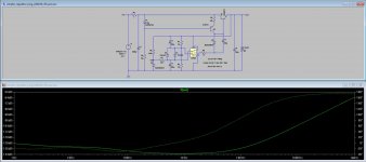
One comment I think it's worth mentioning, even if it may not be accurate. It's amazing, or surprising, to see how the LTSpice sim curves resemble the Super Regulator curves John Walton got.
Now let's start with the apparently tricky AD797. Everybody mentions its instability and tendency to oscillate in the Super Reg since day one, since first WJ article series. Is there a definitive way to tame it?
I do have a few DIP-8 AD797 from the days samples were distributed, and if there's a way to try them and not burn anything, I would love to to listen to them and make comparisons.
Now, the first thing I started with the AD797 is that it's got more terminals than the opamps I have been dealing until now. Or at least one more called Decomp. No one ever mentioned it, so I guess it's useless here.
Any other things to be added to simulating with the AD797 that should be considered, like always use it with a pre-reg, or never use it with a pre-reg, or always bypass the power legs with so and so.
There are two things that make Walton analysis interesting: the listening results, the noise measurements and impedance measurements at the end, where he compares a very few opamps. Two are not made any more: LME49710 and OPA134.
So which are best options left for the Super Reg.
That Decomp pin is critical here.
As you said, the 797 has a tendency to instability, and a comp cap can help here.
But this type of instability is unlikely to be modelled correctly by LTspice as it depends on parasitic capacitances and inductances of the actual implementation.
Jan
As you said, the 797 has a tendency to instability, and a comp cap can help here.
But this type of instability is unlikely to be modelled correctly by LTspice as it depends on parasitic capacitances and inductances of the actual implementation.
Jan
Last edited:
OK, now the bug got me. And I started to make more models from .cir files. Hopefully it will be another stage in the learning curve.
Creating a unique symbol for every device (subcircuit) you use is very inefficient. This is manageable if you only use a few devices over and over but will eventually become overwhelming as you acquire more models. I have hundreds of models for various devices and I can't imagine having to deal with a special symbol for every one of them. As mentioned earlier in this thread, the .inc and .lib directives are the most efficient way to use third-party models in your simulations. I do suggest that you try to grasp that concept because it will make things much easier down the road.
It would be great if you could explain your methodology more in detail, as it may proof interesting to me too.
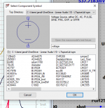
As long as you have a subcircuit file for your device (as you do if you are creating a custom symbol for it), then the process for including that device is straightforward. Draw your schematic with the built-in LTspice symbols, rename the instances to match the subcircuit names, and include the model or library files on the schematic with the .inc or .lib directives. If you examine the files I provided in my post #2354 this might begin to make sense.
Ray said:
Creating a unique symbol for every device (subcircuit) you use is very inefficient. This is manageable if you only use a few devices over and over but will eventually become overwhelming as you acquire more models. I have hundreds of models for various devices and I can't imagine having to deal with a special symbol for every one of them. As mentioned earlier in this thread, the .inc and .lib directives are the most efficient way to use third-party models in your simulations.
Ray, I respectfully disagree. Whenever I import a 3rd party model, I auto-create the symbol and save that in my 'my symbols' folder. It just takes a few moments, and I end up with a library of symbols that have names for the part they represent. Exactly like the list of parts whenever you look in an LTspice list. No need to bother with .incs or including complete netlists on the schematic.
I really don't see your method as easier or faster. But I realize this may be a personal preference.
Jan
Attachments
Yes, we can agree to disagree. 🙂 But I think it's useful for new users to know that there is more than one way to accomplish something in LTspice. Then they can decide for themselves what method suits them the best.
Last edited:

Quick question - when recreating the example from the beginning of this tutorial (4/ Simulating a one transistor Amplifier. Post #14 and 16.)
I get a 100x the BW, so the drop-off of Vout happens around 100MHz instead of 1 MHz.
Any idea why that is? I tried LTSpice IV & XVII, and it's exactly the same schematic.
BR
PS: a bit down the road, I don't get the exact same FFT graphs either (/5 Distortion and FFT). I get same harmonics & roughly same THD calculation, but the graph looks much different in detail.
Make sure you are using the same device as in the original sim. Post #16 shows a 2N2222 and also a 2N3055.
Thanks Mooly, I tried with your 'One transistor amplifier.raw' and get the same result. Possible, that the model for 2N2222, that they include, has changed??
Can't imagine why the circuit suddenly should have so much more BW

Can't imagine why the circuit suddenly should have so much more BW
Last edited:
If you change the device to the 2N3055 the response will change. The 2N2222 has much higher gain/bandwidth product.
Looks like both images in post 16 are showing the response for the 2N3055 when the first one was meant to be for the 2N2222. So well spotted 🙂
Guys, anyone know if it is possible to graph the differential of a node waveform? Integral is possible with Ctrl/Click on waveform label (that's how you get RMS value of a waveform), but I need to differentiate a waveform to see the jumps.
Jan
Jan
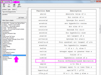
In the Add Plot Trace window,
type d(V(nodename)) to get the derivative of the V(nodename) voltage, with respect to whatever X axis your simulation is using.
.AC you get dV/df
.DC you get dV/dV
.TRAN you get dV/dt
type d(V(nodename)) to get the derivative of the V(nodename) voltage, with respect to whatever X axis your simulation is using.
.AC you get dV/df
.DC you get dV/dV
.TRAN you get dV/dt
That easy huh? Is that documented, didn't find it in the Help file.
I'll check it out, thanks Mark!
Jan
I'll check it out, thanks Mark!
Jan
Can someone tell me if there's something wrong in the OPA134 that I can't make it work?
https://www.ti.com/product/OPA134?u...y2H0A-9TAQ9UcvnW3SBoCq8wQAvD_BwE&gclsrc=aw.ds
https://www.ti.com/product/OPA134?u...y2H0A-9TAQ9UcvnW3SBoCq8wQAvD_BwE&gclsrc=aw.ds
The way to quickly check is, is as follows.
Set up a simple opamp circuit with the OPA134. +/-15V supply, output connected to inv input. Put a 1kHz 1V at the noninv input, and if the output also shows 1V 1kHz, your model is fine.
Jan
Set up a simple opamp circuit with the OPA134. +/-15V supply, output connected to inv input. Put a 1kHz 1V at the noninv input, and if the output also shows 1V 1kHz, your model is fine.
Jan
- Home
- Design & Build
- Software Tools
- Installing and using LTspice IV (now including LTXVII), From beginner to advanced