Brian & Ray,
I will answer and comment over both your advises and uses. Let's see if I can prove a good student.
My suggestion is to take the regulator's asc file and learn how to make it work. Maybe this time I understand it once and for all, and give Jan some relief, who is the one I always ask things, so he must be tired of them.
Here are the asc files and the error message. Where do I start?
Attachments
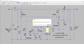
Clearly, this will not work on anyone's machine but yours. See the error window saying it can't open the file? Well, that file, with that path name, is surely not on my PC in that place so it will fail.
If you want to make this portable you must include, together with the .asc, any .asy and any .lib or .mod that is not part of the normal LTspice install.
We can then load all of that in a single folder and run it.
Did you check whether the error file is actually where LTspice looks for it? Did you check the exact spelling of the file, and the exact spelling of the .subckt AD ... line in the .cir? No confusion between - and _ ?
All this has nothing to do with simulation but is straight Windows file management.
Jan
Brian & Ray,
I will answer and comment over both your advises and uses. Let's see if I can prove a good student.
My suggestion is to take the regulator's asc file and learn how to make it work. Maybe this time I understand it once and for all, and give Jan some relief, who is the one I always ask things, so he must be tired of them.
Here are the asc files and the error message. Where do I start?
No idea what you are doing, but when taking the right steps as Jan has shown you, the circuit functions as expected.
The AD825 is not causing any trouble, so try harder.
Hans
Attachments
Carl, I think you are fighting the circuit, as if there is something wrong with it. There isn't, you have issues with files and folders, the Windows environment.
Forget about the circuit for now.
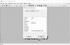
Did you do what I said, from within LTspice, open the AD825 .asy, right-click on it, then in top of the screen click Edit|Attributes|Edit Attributes ? There you will see the path and file name LTspice will go to, expecting to find the subcircuit.
Make sure that is correct.
Jan
Forget about the circuit for now.
Did you do what I said, from within LTspice, open the AD825 .asy, right-click on it, then in top of the screen click Edit|Attributes|Edit Attributes ? There you will see the path and file name LTspice will go to, expecting to find the subcircuit.
Make sure that is correct.
Jan
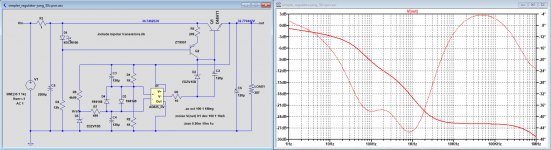
I did not notice that you had changed the V- and the Output, so I corrected this.
The other thing that I noticed is that you use the In- for the reference voltage and the In+ for the feedback.
This is wrong and should be interchanged in your circuit.
So here is the simulation again with the corrections.
Hans
The other thing that I noticed is that you use the In- for the reference voltage and the In+ for the feedback.
This is wrong and should be interchanged in your circuit.
So here is the simulation again with the corrections.
Hans
Attachments
Now it is my turn ;-)
Does anyone know the right syntax for a current controlled current source? I understand there is a gain value, as well as the name of the voltage source whose current is the input to the CCCS.
The Help file doesn't give me the required info (or I don't get it, maybe).
Jan
Does anyone know the right syntax for a current controlled current source? I understand there is a gain value, as well as the name of the voltage source whose current is the input to the CCCS.
The Help file doesn't give me the required info (or I don't get it, maybe).
Jan
Jan,
It’s function is already included in the name, but you may be looking for some more, so can you tell what this is ?
Hans
It’s function is already included in the name, but you may be looking for some more, so can you tell what this is ?
Hans
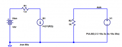
Here you go, Jan.
There are more than one way to accomplish your goal; I chose to use a "Behavioral current source" (LTSPICE builtin symbol "bi"). It lets you type
I just made this example CCCS output 3x the current flowing in resistor R2. You could type bigger and more complicated functions, of course.
Long-time LTSPICE users will ruefully note that the "associated reference direction" for I(Rn) does not appear on the symbol, so trial-and-error are necessary. You can fix this (and SPICE2G6 DID fix this) by forcing yourself to always ALWAYS make the controlling current flow in a zero volt voltage source. A voltage source DOES have an associated reference direction so you always know in advance, which way is +current.
_
There are more than one way to accomplish your goal; I chose to use a "Behavioral current source" (LTSPICE builtin symbol "bi"). It lets you type
- I = (any mathematical function of node voltages and device currents)
I just made this example CCCS output 3x the current flowing in resistor R2. You could type bigger and more complicated functions, of course.
Long-time LTSPICE users will ruefully note that the "associated reference direction" for I(Rn) does not appear on the symbol, so trial-and-error are necessary. You can fix this (and SPICE2G6 DID fix this) by forcing yourself to always ALWAYS make the controlling current flow in a zero volt voltage source. A voltage source DOES have an associated reference direction so you always know in advance, which way is +current.
_
Attachments
Last edited:
I did not notice that you had changed the V- and the Output, so I corrected this.
The other thing that I noticed is that you use the In- for the reference voltage and the In+ for the feedback.
This is wrong and should be interchanged in your circuit.
So here is the simulation again with the corrections.
Hans
Hans,
Can you upload the .asc file so I can compare with mine?
Did you do what I said, from within LTspice, open the AD825 .asy, right-click on it, then in top of the screen click Edit|Attributes|Edit Attributes ? There you will see the path and file name LTspice will go to, expecting to find the subcircuit.
Make sure that is correct.
Jan,
Everybody calls me Carl, but my name is Carlos. Very Latin. Mart is for Martinez. Even more Latin.
OK, I did exactly what you said, and it shows this path I am showing, certainly not selected by me.
So do I edit that path to where the .asy file is?
Attachments
Sorry Carlos, but asking this question means that you still haven’t understood the concept .
My .asc file is your .asc file with the exeption of the two 15V zeners that I did not have available.
But the AD825 in my circuit diagram is just as worthless for you as your AD825 in my simulation because our directories are incompatible.
Jan already mentioned this.
Hans
My .asc file is your .asc file with the exeption of the two 15V zeners that I did not have available.
But the AD825 in my circuit diagram is just as worthless for you as your AD825 in my simulation because our directories are incompatible.
Jan already mentioned this.
Hans
I can see that you are struggling with this so I have attached a corrected .asc file along with a library file that contains all of the models used in your schematic. Note that the opamp symbol is the generic opamp2 included with LTspice. Also note the .lib directive that loads the attached library file.
Place the library file in the same folder as the .asc file and you should be OK. I hope this is helpful.
Place the library file in the same folder as the .asc file and you should be OK. I hope this is helpful.
Attachments
Jan,
Everybody calls me Carl, but my name is Carlos. Very Latin. Mart is for Martinez. Even more Latin.
OK, I did exactly what you said, and it shows this path I am showing, certainly not selected by me.
So do I edit that path to where the .asy file is?
Just edit that line! And you ARE editing the .asy, you want to point it to where the sub-circuit is.
An .asy is just a drawing and has no significance, it can be any drawing, a box, a car, a tree! The ONLY significance are the connection points with the numbers and the subcircuit or model it points to, that will be connected by LTspice to the .asy pins.
Jan
Last edited:
Can I ask for more help to understand the concept?
Carlos,
I’ll turn the question 180 degrees in your direction.
You want to use a AD825 in your circuit diagram, right ?
Just write down in plain text step by step all the steps you took trying to get this done, and we will tell you what was wrong or incomplete.
But maybe by writing it down you will see yourself where you made a step in the wrong direction.
Hans
Well, first of all I want to thank all that have been patient enough and so generous to help me grab the concept into my old ignorant head.
Brian, Hans, Jan, Ray, and sorry if I might be forgetting some name.
Agree with what Hans is proposing. Perhaps I should stick to what I have been trying to do to make the AD825 work.
I followed two paths: one with the .asy file and the other with the .cir file, using the so files that had been uploaded.
First I put the AD825.cir file in my LTSpice program folder.
Then tried to follow these instructions, but I didn't get much long.
LTspice: Simple Steps to Import Third-Party Models | Analog Devices
Then I opened that file with LTSpice, which opened the Macro model.
Then I clicked over subckt > create symbol which asks a question and then opens the rectangular symbol.
Then I edited the numbers to In +, In-, V+, V- and Out, as the instructions show. Then I saved it.
Apparently it was saved as AD825.asy
Then I selected the part from the AutoGenerated directory and put it on the file.
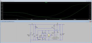
And to my surprise... everything seems to be running smoothly!
But now I wonder why Ray got a better curve than the one I got for psrr?
Please feel free to criticize me, because I don't know where I lost my path and looked so bad.
Brian, Hans, Jan, Ray, and sorry if I might be forgetting some name.
Agree with what Hans is proposing. Perhaps I should stick to what I have been trying to do to make the AD825 work.
I followed two paths: one with the .asy file and the other with the .cir file, using the so files that had been uploaded.
First I put the AD825.cir file in my LTSpice program folder.
Then tried to follow these instructions, but I didn't get much long.
LTspice: Simple Steps to Import Third-Party Models | Analog Devices
Then I opened that file with LTSpice, which opened the Macro model.
Then I clicked over subckt > create symbol which asks a question and then opens the rectangular symbol.
Then I edited the numbers to In +, In-, V+, V- and Out, as the instructions show. Then I saved it.
Apparently it was saved as AD825.asy
Then I selected the part from the AutoGenerated directory and put it on the file.
And to my surprise... everything seems to be running smoothly!
But now I wonder why Ray got a better curve than the one I got for psrr?
Please feel free to criticize me, because I don't know where I lost my path and looked so bad.
Attachments

Carlos,
I think you are going to find that no matter what question you ask here you are going to get a number of different suggestions for how to proceed. The approach you are taking is to start with a subcircuit file and create a custom symbol for it. I do the opposite: I use a generic symbol and can attach any number of devices to that symbol without creating a folder full of symbols that can only be used with one device. To me, it's much easier to just include the appropriate subcircuit or library file and use the symbols that are already available.
The only time I would be inclined to create a custom symbol for a device would be if that device model had a non-standard pin order which was incompatible with the generic built-in symbol. But even in that case, I typically modify the model to match the symbol, instead of the other way around.
But the important thing is that you got your simulation working. Congratulations!
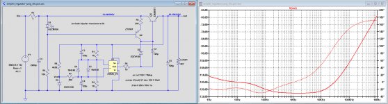
Carlos, you still have the two inputs wrong, they should be interchanged.
Of course you're right, Hans. Schematic has been corrected, and now I get the same psrr as Ray's.
- Home
- Design & Build
- Software Tools
- Installing and using LTspice IV (now including LTXVII), From beginner to advanced