But there are significant differences in your two versions.
The one you have just posted will droop at HF because the opamp is trying to drive the 15.4 ohm resistor via the feedback network.
The one you have just posted will droop at HF because the opamp is trying to drive the 15.4 ohm resistor via the feedback network.
Sorry again, i forgot that 15.4 ohm resistor i modified for Hans.Obviously that didn't modify the response in the audio band.Thanks 🙂
I can see you've had a lot of useful replies...
Although I don't dabble in RIAA circuits I can't really see an issue here. The opamp output is fine up to and beyond the audio band but then it will all fall to pieces because you are running the opamp at effectively unity gain once you get up to a couple hundred kHz. The opamp model may not even be that good at those extremes. You really need a band limited input signal I suspect.
Here is an inverse RIAA network I used together with feedback values from the LM4562 data sheet.
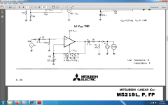
So i have two simulations , one with my filter, one with lm4562 datasheet you presented , both used on the bare datasheet schematic that was used to actually measure M5219 op-amp performance which i happen to have used these days in a preamp for which i will make a thread soon. M5219 is a 6.5v/us slew rate op-amp, no fast op-amp like lt1115 or others like fet input LT1792 which give similar results.
Attachments

Dreamth,
As already said, you think to know everything better.
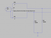
Say the Riaa network has impedance Z.
Then the gain of the amp is 1+Z/R10 = (R10+Z)/R10.
So R10 has become part of the Riaa network.
Use a Laplace Riaa function with a VCVS behind your anti Riaa and you will see how far off it is.
Hans
As already said, you think to know everything better.
Say the Riaa network has impedance Z.
Then the gain of the amp is 1+Z/R10 = (R10+Z)/R10.
So R10 has become part of the Riaa network.
Use a Laplace Riaa function with a VCVS behind your anti Riaa and you will see how far off it is.
Hans
Thank you! I guess i simply worked on the wrong LtSpice for the last two years or so...At some point somebody told me that a simulation i posted a few months ago didn't sim the same way in his LtSpice although he had an old version too...Maybe mine was corrupted...Either way i ran so many simulations for a project that i get the correct answer in the end even if a particular sim is wrong.If you copy the circuit and run both together you will see that the input voltage is different for each with using different RIAA networks and impedances.
Hi Demian.
That's it.
I suppose you used this for a floating 10R MC Cart.
For a single ended application the use of it becomes even simpler.
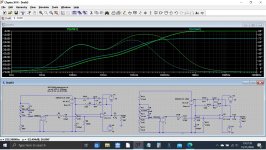
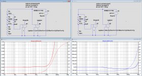
I compared in the image below the Anti Riaa circuit used in the earlier postings to the ideal Laplace curve.
I did it for both the original circuit and the one without 1910R and 563R.
As can be seen, this makes massive difference.
The second one is almost flawless up to 1Mhz and can also be used in transient analysis, where the Laplace function is less reliable.
Hans
That's it.
I suppose you used this for a floating 10R MC Cart.
For a single ended application the use of it becomes even simpler.
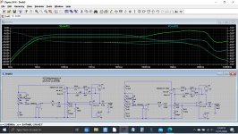
I compared in the image below the Anti Riaa circuit used in the earlier postings to the ideal Laplace curve.
I did it for both the original circuit and the one without 1910R and 563R.
As can be seen, this makes massive difference.
The second one is almost flawless up to 1Mhz and can also be used in transient analysis, where the Laplace function is less reliable.
Hans
Attachments
Friends, an idiosyncrasy in LTspice that kept me running around in circles for a couple of days.
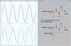
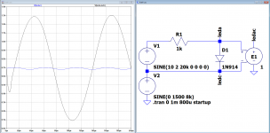
Working on my ESL direct-drive amp, using an optocoupler to isolate two parts of the circuit. I noticed that there seemed a very strange relation between the LED current and the LED voltage. Assuming enough bias current, the signal current into the diode and the voltage across the diode should have substantially the same shape, but that was not the case; the two signals looked almost completely different!
Long story short: if you have such a circuit floating on a high common mode voltage, like a few kV, you will find part of that voltage back across the LED. That is, if you run LTspice with the usual modified trap integration method.
See the first graph - the voltage across the diode is related to the CM voltage and not to the current through the diode! Weird.
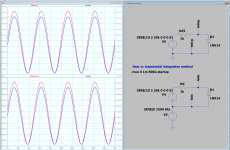
Now, if you switch to the gear or trap method, it looks as expected, see the 2nd graph.
Too bad Mike E is no longer involved with LTspice ...
Jan
Working on my ESL direct-drive amp, using an optocoupler to isolate two parts of the circuit. I noticed that there seemed a very strange relation between the LED current and the LED voltage. Assuming enough bias current, the signal current into the diode and the voltage across the diode should have substantially the same shape, but that was not the case; the two signals looked almost completely different!
Long story short: if you have such a circuit floating on a high common mode voltage, like a few kV, you will find part of that voltage back across the LED. That is, if you run LTspice with the usual modified trap integration method.
See the first graph - the voltage across the diode is related to the CM voltage and not to the current through the diode! Weird.
Now, if you switch to the gear or trap method, it looks as expected, see the 2nd graph.
Too bad Mike E is no longer involved with LTspice ...
Jan
Attachments
Last edited:
Hi Jan,
What a strange thing you discovered, but at the same time you found a solution.
With 100nsec timestep I get the image below, but when using 10nsec everything is fine without having to use gear.
Hans
What a strange thing you discovered, but at the same time you found a solution.
With 100nsec timestep I get the image below, but when using 10nsec everything is fine without having to use gear.
Hans
Attachments

Last edited:
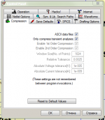
The easiest way to get the right result with the modified trap method is to change the output RAW file format.
Attachments
Last edited:
Hi Alexander, really is that going to change it? That is very curious!
Makes you wonder what else there is we don't know!
Jan
Makes you wonder what else there is we don't know!
Jan
The disadvantage of this method is that you get a bigger RAW file. The output file will not be compressed and it is not binary.
Although there are other spice-programs. They form ASCII raw files.
Although there are other spice-programs. They form ASCII raw files.
Attached is a Laplace RIAA source. I thought this would be the easiest place to start. This was for testing a simulation of an ultra high end RIAA stage. The sim and the measured performance tracked really close.
Thank you both!Hi Demian.
That's it.
I suppose you used this for a floating 10R MC Cart.
For a single ended application the use of it becomes even simpler.
I compared in the image below the Anti Riaa circuit used in the earlier postings to the ideal Laplace curve.
I did it for both the original circuit and the one without 1910R and 563R.
As can be seen, this makes massive difference.
The second one is almost flawless up to 1Mhz and can also be used in transient analysis, where the Laplace function is less reliable.
Hans
The disadvantage of this method is that you get a bigger RAW file. The output file will not be compressed and it is not binary.
Although there are other spice-programs. They form ASCII raw files.
Yes I noticed. There is a perceptive delay while the .raw is loading before graphing. But a very small price to pay.
How do you find out these things??
Jan
I did it for both the original circuit and the one without 1910R and 563R.
As can be seen, this makes massive difference.
The second one is almost flawless up to 1Mhz and can also be used in transient analysis, where the Laplace function is less reliable.
Hans
It's you who sugested that i should remove the 536 ohm along with the 1910 ohm resistor which cannot be done when testing an mm cart with that antiriaa network .You remained silent on that and tried to transfer your mistake on me, which is not fair.There is nothing wrong with your LTSpice.
Start by using a decent Anti Riaa network.
Eliminating the top 1910R and the 536R below will give a proper Anti Riaa response.
Hans
Using Laplace functions is not my speciality, i'm not a mathematician as you are , but you cannot remove 536 ohms resistor of that antiriaa network and drive an mm cart in that configuration .
I saw in one of your cart simulations the use of a 4.75Kohm resistor and 100pF capacitor loading an mm cart like Shure v15 type 3.
The manufaturer recommended value is 47k ohms and 4...500pf. Perhaps Shure engineers were stupid and couldn't understand Laplace functions...
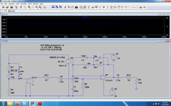
With that supposedly faulty antiriaa network and the one recommended by Tuner[the same with the one used in lme49710(4562) phono found in its datasheet ] in the photo below I made real measurements without a cartridge on a 60MegHz oscilloscope and i got good reproductions(visually) of 20...25 khz square waves actually more of trapezoid signals, not perfect squares due to some imperfections of my signal generator loaded by the antiriaa network and input resistor/capacitor of the phono preamp , but perfectly reproduced as well as the reproduction of up to 480khz sinus signals where the sinus got visibly tilted.Unfortunately the proof for that vanished away with Tinypic site deleting pictures that were posted here:
UNU-pnono riaa mm preamp
It should be clear from that topic that at least starting with 2018 i used that last antiriaa network in simulations and stopped measuring the real thing with a scope as i already trust it.Both antiriaa networks did the job so seeing those measurements on a scope with my own eyes cannot make me trust your mathematics more, but i'll try understand some of it maybe in the future when i'll be able to hear 1Mhz.
Few clarifications are needed though: the phono preamp i designed in 2014 was using passive riaa, no op-amp , 1.3 gigaHz valves and diamond buffers current drive so very high speed circuits.
That being said , i trust @Molly more , when saying that it's actually the op-amp gain with frequency that's doing that anomally , and not the Anti-Riaa itself.
You may be good mathematicians, but i'm a test and fix guy and throughout the years i got a lot of faulty designs under my lenses and modified in order to work.
I enjoy a lot simple simulations that guys likeme can understand for a bit because i can dismiss my scope for longer , but having two simulations giving different results with different LtSpice versions starts deteriorating my trust in these mathematical instruments .
So I appealed to you because guys like you built those simulators , but when you ask me to modify a perfectly working antiriaa network, take my word, i will not do it because i'm the guy downstairs running the Test department fixing the stuff you design.
Attachments
Last edited:
I have sinds a new hardisk no more problems with ltspice.
I did discover because kicad did crash all the time because of very slow read of disk.
now It does fine already for some weeks.
I did discover because kicad did crash all the time because of very slow read of disk.
now It does fine already for some weeks.
...
Too bad Mike E is no longer involved with LTspice ...
Jan
This is not going to cure it, just a little note.
I do think that the simulation is not the problem, for mee it looks like that the plotting routines are the problem.
Frans.
Attachments
Hi Alexander, really is that going to change it? That is very curious!
Makes you wonder what else there is we don't know!
Jan
http://web.stanford.edu/group/cslip...erger-corpus/On-What-We-Know-We-Dont-Know.pdf
- Home
- Design & Build
- Software Tools
- Installing and using LTspice IV (now including LTXVII), From beginner to advanced