Thanks OS good work, do not understand why this amplitude ({sprt(2)})?
Window in which used fft ? I have an article in portuguese it has windows for measuring instruments in fft, I put only the table
Note:Leakage, behavior is not predictable where the signal is not zero(Ex: pink noise) this"leakage"just damaging the samples following.
Table:
Window in which used fft ? I have an article in portuguese it has windows for measuring instruments in fft, I put only the table
Note:Leakage, behavior is not predictable where the signal is not zero(Ex: pink noise) this"leakage"just damaging the samples following.
Table:
Attachments
Thanks OS good work, do not understand why this amplitude ({sprt(2)})?
Not my work,man. Andy c. (the LT master) is the creator..
Perhaps he can explain sqrt (2) and the different
type windows you have presented. Curious ???
OS
Oh, that sine_gen.zip is just something I threw together real quick to help OS troubleshoot a problem he was having with a high FFT residual a while back. It wasn't meant as some kind of model for how to do things in the most general way. I've attached a new one in which the frequency and number of FFT points are parameters, which makes it more general. The one OS posted works best only at 1 kHz.
The idea is to have the max time step be one period divided by (num_FFT_points - 1). I've also set it up to do an automatic THD calculation without having to do an FFT from the graphs. Run the sim and do a view, SPICE error log to see the zero percent distortion of the source in text form.
When doing an FFT from the graph, LTspice chooses 0 dB as 1 VRMS. Since 1 VRMS is sqrt(2) Volts peak, that's what I chose for the amplitude of the source. So when you do the FFT from the graph, the source will be normalized to 0 dB.
Edit: OS, I think you put the old sine_gen.zip on your site? I hadn't meant it for reference, just a quick fix. The one attached to this post is more general.
Attachments
I hadn't meant it for reference, just a quick fix.
thanks, andy, that is way cool..(attached) the old one still is WAY
better than a standard source , but this one takes the cake..😀
Os
Attachments
I was just wondering, after simulating my new "baby".., could
one comment out a verbose distortion log ?? (H2 - H7)
looking at the data , it seems as the distortion readout sums
the fourier phases. could comments be added to give H2 , 3,5
and 7 , too ??
I can see my h2 and 3 here, (the 2 e-05's)
Fourier components of V(c)
DC component:0.041085
Harmonic Frequency Fourier Normalized Phase Normalized
Number [Hz] Component Component [degree] Phase [deg]
1 1.000e+03 8.060e+00 1.000e+00 -0.40° 0.00°
2 2.000e+03 1.979e-05 2.455e-06 -101.51° -101.11°
3 3.000e+03 1.991e-05 2.470e-06 -103.13° -102.74°
4 4.000e+03 6.748e-06 8.372e-07 157.60° 157.99°
5 5.000e+03 3.251e-06 4.033e-07 -122.74° -122.34°
6 6.000e+03 5.045e-06 6.260e-07 165.93° 166.33°
7 7.000e+03 3.725e-06 4.621e-07 88.48° 88.87°
8 8.000e+03 3.740e-06 4.641e-07 169.05° 169.45°
9 9.000e+03 5.324e-06 6.606e-07 84.85° 85.25°
Total Harmonic Distortion: 0.000377%
OS
Thanks Andy
I wonder if it is possible obtain separate graphics of harmonics(2nd, 3rd, ...)Mag versus spectrum (20 and 20KHz)
This web , (4 fig) author used EWB:
http://www.geocities.com/ResearchTriangle/Node/2356/scheminf1e.html
I found these calculations that web, do not know if this related, with get graphics separated from the harmonics ?
http://www.allaboutcircuits.com/vol_2/chpt_7/2.html
ostripper said:I was just wondering, after simulating my new "baby".., could one comment out a verbose distortion log ?? (H2 - H7)
Hmm, I'm not sure what you mean by that. Could you explain a bit more? The number of harmonics defaults to 9 if not specified. You can specify the number of harmonics you want displayed and included in the calculation. See the docs of ".FOUR" for how to do this.
looking at the data , it seems as the distortion readout sums the fourier phases. could comments be added to give H2 , 3,5 and 7 , too ??
The Fourier phases don't play any part in the THD calculation. THD is calculated by taking the square root of the sum of the squares of the distortion component amplitudes, dividing that by the amplitude of the fundamental, and multiplying by 100 to get percent.
I might be misinterpreting your question though. I don't know of any way to change the distortion display in the error log other than specifying the number of harmonics that's included.
Rafael.luc said:I wonder if it is possible obtain separate graphics of harmonics(2nd, 3rd, ...)Mag versus spectrum (20 and 20KHz)
I don't know of any automated way to do this in LTspice. If you want to simulate distortion over many frequencies, you can change this statement:
.param freq 1k
to:
.step param freq (options for .step command here)
See the documentation for .step for how to specify start value, stop value, increment, etc. You can do logarithmic steps, step in a list, etc. You'll want to change the stop time in the simulation to something like {20/freq} to give 20 cycles no matter what freq is.
Then the SPICE error log will have a table of harmonics for each frequency. I have plotted these in the past by pasting them into Excel. I don't know of any clean way to do this.
There is an automated way to do all that.
Look in the LTSpice forum, libraries, all that, and you will find that way.
Using a little Perl program the simulation is run as many times you need then the results are collected so that they can be shown.
Look in the LTSpice forum, libraries, all that, and you will find that way.
Using a little Perl program the simulation is run as many times you need then the results are collected so that they can be shown.
I noticed that a while back, but it looks like it only plots THD vs. a parameter. If I understood correctly, Rafael was asking about individual harmonics (see his links).
Yes, really be separated!!!andy_c said:If I understood correctly, Rafael was asking about individual harmonics (see his links).
The graphics of the first link I that posted, could be of Ecxel or another program (not thought about it!)
[]'s
there's a .FOUR function in LTSpice that has the amplitudes of the harmonics listed in the log file, it should be a simple matter to use that data to plot from.
for example:
Fourier components of V(out)
DC component:45.7587
Harmonic Frequency Fourier Normalized Phase Normalized
Number [Hz] Component Component [degree] Phase [deg]
1 1.000e+03 2.496e-02 1.000e+00 1.79° 0.00°
2 2.000e+03 1.244e-02 4.985e-01 1.15° -0.64°
3 3.000e+03 8.292e-03 3.322e-01 1.06° -0.73°
4 4.000e+03 6.218e-03 2.491e-01 1.09° -0.70°
5 5.000e+03 4.974e-03 1.992e-01 1.19° -0.60°
6 6.000e+03 4.144e-03 1.660e-01 1.31° -0.48°
7 7.000e+03 3.553e-03 1.423e-01 1.43° -0.36°
8 8.000e+03 3.108e-03 1.245e-01 1.58° -0.21°
9 9.000e+03 2.763e-03 1.107e-01 1.72° -0.07°
Total Harmonic Distortion: 73.220745%
Re: Fairchild KSC3503/2SC3503 Model
I'm also having some trouble with that model, though different from nature: An Early voltage of 717.25V.
Given BF=101.5, this means that the figure of merit VAF*BF=72800 !
Is this trannie really that good?
Comments invited.
Regards,
Edmond.
Bob Cordell said:Hi all,
I'm having some trouble running the Fairchild SPICE model for their KSC3503 NPN transistor in LTspice. The model from Fairchild's web site is below:
[snip]
+ VAF=717.25
[snip]
Not sure the best way to proceed with confidence here.
Thanks in advance for any suggestions.
Cheers,
Bob
I'm also having some trouble with that model, though different from nature: An Early voltage of 717.25V.
Given BF=101.5, this means that the figure of merit VAF*BF=72800 !
Is this trannie really that good?
Comments invited.
Regards,
Edmond.
Im not very proficient in spice but I get constant better results using 2sc3423, 2sc1145 and 2sc3600 in real circuits.
These model parameters have me confused , I have models for 2sc3423 where the figure of merit is only 13400, at least in simulation they always outperform the KSC3503 which is true in real circuits. There must be other parameters playing a role here, maybe Andy C could help.
These model parameters have me confused , I have models for 2sc3423 where the figure of merit is only 13400, at least in simulation they always outperform the KSC3503 which is true in real circuits. There must be other parameters playing a role here, maybe Andy C could help.
Hi Alex,
Thanks for your input. However, what do you mean by better? I hope lower distortion and not something vague like 'sonically' better.
The 2SC3423/2SA1360 pair has nice specs, but is a bit too 'small' for my application. The 2SC3600/2SA1406 pair, however, looks very promising.
Does anyone know a reliable source in Europe for these components? (i.e. the original Sanyo's, no fake or second source)
Regards,
Edmond.
Sorry the 2sc1145 should read 2sc2705, lower measured distortion results when used as vas, the 2sc3600 and 2sc2705 give best results but the latter cant handle much power. Also sanyo 2sa1380 and 2sc3502 excellent, slightly lower power than 3503 but better than 2705 or 3423.
Ive never tried but how about 2 in parralel, is there any problem doing this???
Its risky and hard to find them in europe, I was lucky to get some old stock here from a shop, the owner wanted to get rid of them, and sold his last 27 pairs to me at 1.20 Euros a pair.
Try MCM electronics, they are pretty reliable, I see they have stock and well priced, the shipping charges is a pain though. List price is around 2 dollars a pair. If you lucky they have them the way Sanyo used to ship, factory matched pairs, the pairs I bought here were matched to closer than 5 percent in hfe and VBE, also all NPN were within 5 percent and the PNPs likewise, reason I have strong preference for buying Sanyo devices although its very very difficult to find them in original factory packaging.
I used Renardson s test method for small signal and medium signal devices some years back, you can have a look at the method in his site.
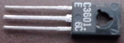
I have just compaired to one other sanyo devices I have here, if its not original its the best copy Ive every seen, the front marking style is identical to mine, and has the line accross the right hand corner circle, something a contact at sanyo told me to look out for.
The circles look a bit bigger and more shallow but this could be because of the pic. Ill take a pic of mine with webcam, see how this comes out but Ill have to reboot to install cam drivers.
Pity Im looking for some too, Im waiting for a contact which is trying to locate some in Asia. I can still find the odd loose ones here but matching is problem, would have to match gain groups to get even close. Dalbani in uk also sells authentic but they expensive.
Sorry Edmond the cam is useless for this, cant focus close up but Ill say with 99,999 percent surity thats the real deal. Even the face where the markings are is slightly lighter in colour, that widening at the top of just the middle pin is identical and the lettering is identical in style too. All my sanyos look like this and most came direct from factory through a agent to me.
Re: Re: Fairchild KSC3503/2SC3503 Model
Hi Edmond,
I one believes the Fairchild data sheet, and if I am not mistaken, those transistors are that good.
From the data sheet, at a collector current of about 10 mA and a base current of 60 uA, we have Ic=10 mA @ 100V and Ic=9.5 mA @ 35V. This translates to an output resistance ro of 130k at 10 mA. Using the approximation ro = VA/Ic, we get VA = 1300V.
Note at this point beta is 10mA/60uA = 167.
This all translates to a FOM of 217,000.
I know; hard to believe. Unless of course I've screwed up here somehow.
Cheers,
Bob
Edmond Stuart said:
I'm also having some trouble with that model, though different from nature: An Early voltage of 717.25V.
Given BF=101.5, this means that the figure of merit VAF*BF=72800 !
Is this trannie really that good?
Comments invited.
Regards,
Edmond.
Hi Edmond,
I one believes the Fairchild data sheet, and if I am not mistaken, those transistors are that good.
From the data sheet, at a collector current of about 10 mA and a base current of 60 uA, we have Ic=10 mA @ 100V and Ic=9.5 mA @ 35V. This translates to an output resistance ro of 130k at 10 mA. Using the approximation ro = VA/Ic, we get VA = 1300V.
Note at this point beta is 10mA/60uA = 167.
This all translates to a FOM of 217,000.
I know; hard to believe. Unless of course I've screwed up here somehow.
Cheers,
Bob
- Home
- Design & Build
- Software Tools
- Spice simulation